Data Sizes
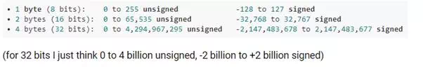
Before we start talking about time delays, this is probably as good a place as any to examine and emphasize the range of values that can be represented by data variables of different byte sizes. These are numbers that μC programmers will deal with throughout their careers, so get to know them well:
SIMPLE TIME DELAYS
While there are many ways to execute time delays and generate time intervals, the simplest (but not the best) is a software delay. This just involves sitting in a do-nothing loop for the desired length of time, and then exiting the loop. Since microcontrollers are so fast, a one-second delay may loop hundreds of thousands or millions of times. These are hundreds of thousands or millions of CPU clock cycles that are being wasted, not available for doing any other useful work. For this reason, software delays are not generally a good idea, even though they are easy to understand for beginners.
For a suitable LED blink rate, a useful rule of thumb for estimating how many times a software delay should loop is to divide the μC clock rate by 100. Use this count for both the LED ON and OFF times, so the total LED delay for one blink cycle is twice this value. Thus an AVR running at 1MHz would delay loop 10,000 times while ON, then 10,000 times while OFF, and the STM32 running at 8MHz would delay loop 80,000 times ON and the same number OFF. This is just a rule of thumb, of course, and the numbers can be increased or decreased, but it's a really easy number to calculate, and it generally gives a number that results in a good blink rate. A good blink rate is simply one where the total blink period is not so small that the LED blinks too fast to notice it is blinking (say 20 or more times per second), nor so large that the LED takes many seconds to blink, forcing you to sit and stare at it to see if your program is working at all.
AT LAST, IT BLINKS! (AVR VERSION)
It's taken a while to lay the groundwork, but we're finally ready to blink our danged LED. We will write our LED blinky program in C, and follow up with ASM versions in a future tutorial chapter.
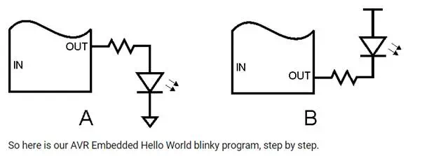
For the AVR, the C LED blinky program is dead simple, largely because the total AVR initialization is one line of code. For the STM the actual blinky code is identical, but the configuration is a bit more complex. Both the STK-500 and the STM32VLDiscovery boards have built-in LEDs, but if you're using some other hardware that doesn't have any built-in LEDs you'll need to wire one in. We will talk more about this in a future chapter, but for now you can just connect your chosen GPIO pin to a resistor of around 470 - 1000 Ohms, connect the other end of the resistor to the anode of the LED, and connect the cathode of the LED to ground (GND). For future reference, this makes your LED "active high." To test your LED wiring, disconnect power to the board, remove the resistor lead from the GPIO pin and connect it to Vcc or Vdd (the same voltage that powers your microcontroller), then apply power. The LED should light up. Once you've confirmed your LED wiring is good, disconnect power, remove the resistor lead from Vcc/Vdd and reconnect the lead back to the GPIO pin. Under no circumstances have the GPIO pin connected directly to Vcc/Vdd!
Here is a drawing of an LED wired active high (A), and one wired active low (B)
Step 1 - Create Empty Program
Atmel Studio will create an empty program for you, including all the chip-specific data for the microcontroller you specify. If you are using a different compiler, or even a different language, the documentation for the compiler will tell you how to create an empty program.
Step 2 - Add AVR Initialization
Initializing the AVR involves two components: setting up the AVR clock, and configuring the selected GPIO pin as an output. The first of these, setting up the clock, does not involve any program code, but is done by configuring the AVR fuses. For simplicity we will use the AVR clock settings as it comes from the factory. These settings select the internal 8 MHz RC clock, and select a clock divider of 8, resulting in the chip running off the internal clock at a speed of 1 MHz.
Configuring the LED GPIO pin as an output is simplicity itself. Simply write a 1 into the proper bit position of the chosen port. Let's pick bit 0 of port B as our LED pin. Setting this pin as an output takes the following line of code:
DDRB = (1<<0);
This sets the pin corresponding to PORT B bit 0 to an output, and all other PORT B pins to inputs. Or, to leave the other bits of DDRB unchanged (they may have already been set earlier in the program)
DDRB |= (1<<0);
Step 3 - Add a Software Delay Function
The software delay function will take an input value and count that value down to 0, then return. The larger the value the longer it will take to count down to 0, hence the longer the delay.
Depending on the range of input values needed, the input value will either be declared as a 16-bit or a 32-bit variable. As mentioned earlier, on an 8 bit device like the AVR, decrementing a 32-bit variable will take longer than decrementing a 16-bit variable, but this is not really an issue since it can be accounted for by using a smaller delay value.
Using our blink count rule of thumb, our blink delay will take 1,000,000/100 = 10,000 cycle loops (1,000,000 is our AVR clock rate). Remembering our data size vs numeric range table, 10,000 can fit into a 16 bit variable, but later we will speed up our AVR to 8 MHz (and other AVRs can run up to 20 MHz), so we'll use a 32-bit variable to be able to accomodate those higher clock rates. So here is our delay function:
void delay(volatile uint32_t d){ while (d-- != 0) ;}
The declaration of the delay count 'd' sets it to a 32-bit unsigned variable (uint32_t), and also uses the 'volatile' keyword to prevent the compiler from possibly optimizing away the "useless" function (the function doesn't change anything in the program and is therefore unnecessary, in the view of the compiler). Without 'volatile' the entire delay function might get optimized into nothing and your LED would end up blinking hundreds of thousands of times a second.
Step 4 - Write the LED Blink Loop
The obvious way to write the blink loop would seem to be this:
- Turn LED ON
- Delay
- Turn LED OFF
- Delay
- Loop Back
But there's another way that eliminates almost half of the loop code:
- XOR LED bit
- Delay
- Loop Back
The penalty for this method is that the LED ON and OFF times will always be the same, while with the first method one could use different values for the ON and OFF delays. As usual, there's a tradeoff. For our LED blinky we'll use this second method.