Design Of Digital Filters
Prereqisting Discussion
To remove or to reduce strength of unwanted signal like noise and to improve the quality of required signal filtering process is used. To use the channel full bandwidth we mix up two or more signals on transmission side and on receiver side we would like to separate it out in efficient way. Hence filters are used. Thus the digital filters are mostly used in
1. Removal of undesirable noise from the desired signals
2. Equalization of communication channels
3. Signal detection in radar, sonar and communication
4. Performing spectral analysis of signals.
Analog and digital filters
In signal processing, the function of a filter is to remove unwanted parts of the signal, such as random noise, or to extract useful parts of the signal, such as the components lying within a certain frequency range.
The following block diagram illustrates the basic idea.
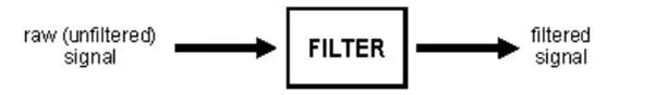
There are two main kinds of filter, analog and digital. They are quite different in their physical makeup and in how they work.
An analog filter uses analog electronic circuits made up from components such as resistors, capacitors and op amps to produce the required filtering effect. Such filter circuits are widely used in such applications as noise reduction, video signal enhancement, graphic equalizers in hi-fi systems, and many other areas.
In analog filters the signal being filtered is an electrical voltage or current which is the direct analogue of the physical quantity (e.g. a sound or video signal or transducer output) involved.
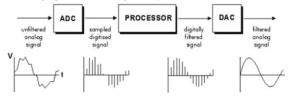
A digital filter uses a digital processor to perform numerical calculations on sampled values of the signal. The processor may be a general-purpose computer such as a PC, or a specialized DSP (Digital Signal Processor) chip.
The analog input signal must first be sampled and digitized using an ADC (analog to digital converter). The resulting binary numbers, representing successive sampled values of the input signal, are transferred to the processor, which carries out numerical calculations on them. These calculations typically involve multiplying the input values by constants and adding the products together. If necessary, the results of these calculations, which now represent sampled values of the filtered signal, are output through a DAC (digital to analog converter) to convert the signal back to analog form. In a digital filter, the signal is represented by a sequence of numbers, rather than a voltage or current. The following diagram shows the basic setup of such a system.
Basic Block Diagram Of Digital Filters
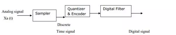
1. Samplers are used for converting continuous time signal into a discrete time signal by taking samples of the continuous time signal at discrete time instants.
2. The Quantizer are used for converting a discrete time continuous amplitude signal into a digital signal by expressing each sample value as a finite number of digits.
3. In the encoding operation, the quantization sample value is converted to the binary equivalent of that quantization level.
4. The digital filters are the discrete time systems used for filtering of sequences. These digital filters performs the frequency related operations such as low pass, high pass, band pass and band reject etc.
These digital Filters are designed with digital hardware and software and are represented by difference equation.
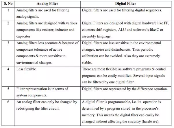
DIFFERENCE BETWEEN ANALOG FILTER AND DIGITAL FILTER