Two Examples Of The Use Of Feedback
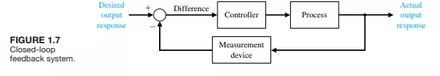
The concept of feedback used to achieve a closed-loop control system was described in Section 1.1 and illustrated by the system of Figure 1.3. Many pioneering engineers have used feedback control systems to achieve the desired performance. The feedback system is shown in Figure 1.7. The difference (that is, the error) between the desired output response and a reasonably accurate measurement of the actual output response is calculated as shown in the figure. The following two examples illustrate the use of feedback to improve the response of a system.
Harold S. Black graduated from Worcester Polytechnic Institute in 1921 and joined Bell Laboratories of American Telegraph and Telephone (AT&T). In 1921, the major task confronting Bell Laboratories was the improvement of the telephone system and the design of improved signal amplifiers. Black was assigned the task of linearizing, stabilizing, and improving the amplifiers that were used in tandem to carry conversations over distances of several thousand miles.
Then came the morning of Tuesday, August 2, 1927, when the concept of the negative feedback amplifier came to me in a flash while I was crossing the Hudson River on the Lackawanna Ferry, on my way to work. For more than 50 years I have pondered how and why the idea came, and I can’t say any more today than I could that morning. All I know is that after several years of hard work on the problem, I suddenly realized that if I fed the amplifier output back to the input, in reverse phase, and kept the device from oscillating (singing, as we called it then), I would have exactly what I wanted: a means of canceling out the distortion in the output. I opened my morning newspaper and on a page of The New York Times I sketched a simple canonical diagram of a negative feedback amplifier plus the equations for the amplification with feedback. I signed the sketch, and 20 minutes later, when I reached the laboratory at 463 West Street, it was witnessed, understood, and signed by the late Earl C. Blessing.
I envisioned this circuit as leading to extremely linear amplifiers (40 to 50 dB of negative feedback), but an important question is: How did I know I could avoid selfoscillations over very wide frequency bands when many people doubted such circuits would be stable? My confidence stemmed from work that I had done two years earlier on certain novel oscillator circuits and three years earlier in designing the terminal circuits, including the filters, and developing the mathematics for a carrier telephone system for short toll circuits.
Another example of the discovery of an engineering solution to a control system problem was that of the creation of a gun director by David B. Parkinson of Bell Telephone Laboratories. In the spring of 1940, Parkinson was a 29-year-old engineer intent on improving the automatic level recorder, an instrument that used stripchart paper to plot the record of a voltage. A critical component was a small potentiometer used to control the pen of the recorder through an actuator.
Parkinson had a dream about an antiaircraft gun that was successfully felling airplanes. Parkinson described the situation.
After three or four shots one of the men in the crew smiled at me and beckoned me to come closer to the gun. When I drew near he pointed to the exposed end of the left trunnion. Mounted there was the control potentiometer of my level recorder!
The next morning Parkinson realized the significance of his dream: If my potentiometer could control the pen on the recorder, something similar could, with suitable engineering, control an antiaircraft gun.
After considerable effort, an engineering model was delivered for testing to the U.S. Army on December 1, 1941. Production models were available by early 1943, and eventually 3000 gun controllers were delivered. Input to the controller was provided by radar, and the gun was aimed by taking the data of the airplane’s present position and calculating the target’s future position.