Design Example: Turntable Speed Control
Many modern devices use a turntable to rotate a disk at a constant speed. For example, a CD player, a computer disk drive, and a phonograph record player all require a constant speed of rotation in spite of motor wear and variation and other component changes. Our goal is to design a system for turntable speed control that will ensure that the actual speed of rotation is within a specified percentage of the desired speed [43, 46]. We will consider a system without feedback and a system with feedback.
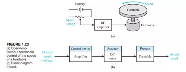
To obtain disk rotation, we will select a DC motor as the actuator because it provides a speed proportional to the applied motor voltage. For the input voltage to the motor, we will select an amplifier that can provide the required power.
The open-loop system (without feedback) is shown in Figure 1.23(a). This system uses a battery source to provide a voltage that is proportional to the desired speed.This voltage is amplified and applied to the motor.The block diagram of the open-loop system identifying control device, actuator, and process is shown in Figure 1.23(b).
To obtain a feedback system with the general form of Fig. 1.9, we need to select a sensor. One useful sensor is a tachometer that provides an output voltage proportional to the speed of its shaft. Thus the closed-loop feedback system takes the form shown in Fig. 1.24(a). The block diagram model of the feedback system is shown in Fig. 1.24(b).The error voltage is generated by the difference between the input voltage and the tachometer voltage.
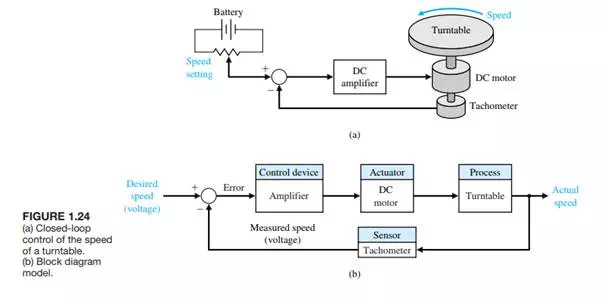
We expect the feedback system of Figure 1.24 to be superior to the open-loop system of Figure 1.23 because the feedback system will respond to errors and work to reduce them. With precision components, we could expect to reduce the error of the feedback system to one-hundredth of the error of the open-loop system.
Design Example: Insulin Delivery Control System
For this and subsequent design examples, we will utilize the design process illustrated in Figure 1.22. In Chapter 1, we develop a preliminary design plan by carrying out steps 1 through 4 of the design process of Figure 1.22. Thus, for this example, we will (1) establish the control goal, (2) identify the variables to control, (3) write the preliminary specifications, and (4) establish one or more possible system configurations.
Control systems have been utilized in the biomedical field to create implanted automatic drug-delivery systems to patients [29–31]. Automatic systems can be used to regulate blood pressure, blood sugar level, and heart rate. A common application of control engineering is in the field of open-loop system drug delivery, in which mathematical models of the dose–effect relationship of the drugs are used. A drug-delivery system implanted in the body uses an open-loop system, since miniaturized glucose sensors are not yet available. The best solutions rely on individually programmable, pocketsized insulin pumps that can deliver insulin according to a preset time history. More complicated systems will use closed-loop control for the measured blood glucose levels.
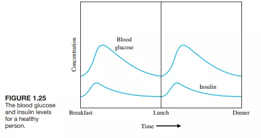
Our goal (step 1) is to design a system to regulate the blood sugar concentration of a diabetic. The blood glucose and insulin concentrations for a healthy person are shown in Figure 1.25. The system must provide the insulin from a reservoir implanted within the diabetic person.
Thus, the variable we wish to control (step 2) is the blood glucose concentration. The specification for the control system (step 3) is to provide a blood glucose level for the diabetic that closely approximates (tracks) the glucose level of a healthy person (Figure 1.25). In step 4, we propose a preliminary system configuration. An open-loop system would use a preprogrammed signal generator and miniature motor pump to regulate the insulin delivery rate as shown in Figure 1.26(a). The feedback control
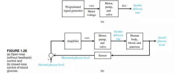
system would use a sensor to measure the actual glucose level and compare that level with the desired level, thus turning the motor pump on when it is required, as shown in Figure 1.26(b).