Source Transformation for Circuits with Inductors and Capacitors
Note that source transformation is also applicable for circuits which have inductors and capacitors. However, in this scenario, one needs to analyze the circuit in the frequency domain.
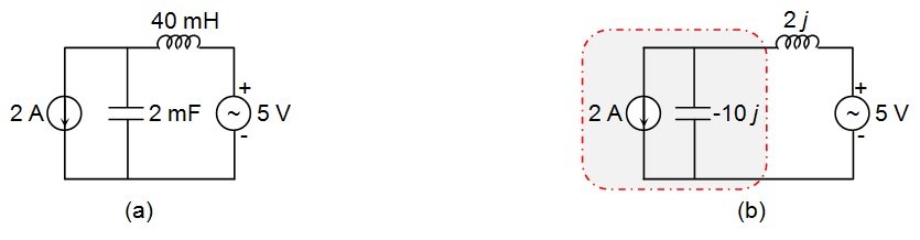
Let's look at the circuit shown in Figure 12(a).
Figure 12
Here, if we assume ω to be 50 rad/s, then
Impedance of 2 mF capacitor = -j/ωC = -j/(50 × 2 × 10-3) = -j/(100 × 10-3) = -10j
Impedance of 40 mH inductor = jωL = j × 50 × 40 × 10-3 = 2j
Now, let us assume that we need to find the voltage across the 40 mH inductor.
When we look at the circuit diagram, it is evident that this process will become easier if we convert the 2 A current source in parallel with a -10j impedance into a voltage source. This process yields V = 2 × (-10j) = -20j directed downwards, in series with a -10j impedance.
The resulting circuit is shown in Figure 13.
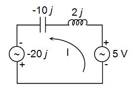
Figure 13
Now, let us apply KVL to the circuit to determine the current I flowing through it.
Thus, the voltage across the inductor VL will be
Conclusion
The analysis presented in this article on source transformation can be summarized in the following three points:
1. Source transformation carried out per the rules shown in Figure 14 can be used to simplify circuits and facilitate mesh analysis.
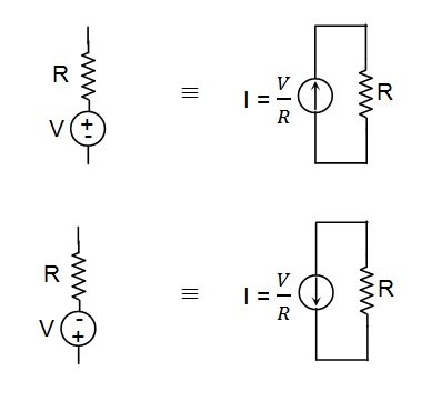
Figure 14
2. Dependent sources can be transformed just like independent sources (Figure 15).
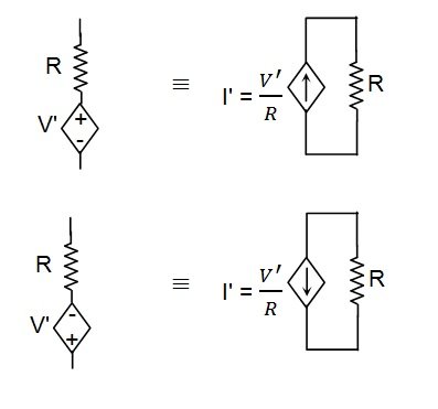
Figure 15
3. The technique of source transformation can even be used to analyze circuits which have capacitors and inductors, provided we analyze them in the frequency domain.
I hope this article has given you a better understanding of source transformation.