Source Transformation for Dependent Sources
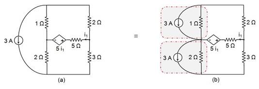
Source transformation is applicable even for the circuits which have dependent sources. Let's consider the circuit shown in Figure 7(a).
Here, one needs to resort to source shifting for the 3 A current source before applying source transformation. This yields the circuit shown in Figure 7(b).

Figure 7
Step 1: Current-to-Voltage Source Transformation
Now let us apply current-to-voltage source transformation for the circuit elements indicated in Figure 7(b).
For the upper portion, we have V = 3 × 1 = 3 V, with the positive terminal oriented downwards, in series with a 1 Ω resistor. Similarly, for the lower portion we get V = 3 × 2 = 6 V, oriented downwards, in series with a 2 Ω resistor. This leads to the circuit shown in Figure 8(a).

Figure 8
The circuit can be further reduced: the upper mesh has a 1 Ω resistor in series with a 2 Ω resistor, forming an equivalent resistance of 3 Ω, and the lower mesh has a 2 Ω resistor in series with a 3 Ω resistor, which can be replaced by a single 5 Ω resistor. This results in the circuit shown in Figure 8(b).
Step 2: Voltage-to-Current Source Transformation
By looking at Figure 8(b), you can see that we need to apply voltage-to-current source transformation three times (once for each source-plus-resistor combination).
Case 1: For the 3 V source in series with 3 Ω
in parallel with a 3 Ω resistor, directed towards the left.
Case 2: For the 5i1 dependent voltage source in series with 5 Ω
in parallel with a 5 Ω resistor, directed towards the right.
Case 3: For the 6 V source in series with 5 Ω
in parallel with a 5 Ω resistor directed towards the right.
These steps lead to the circuit shown in Figure 9.

Figure 9
Here, the two independent current sources are oriented in opposite directions and thus can be replaced by a single current source whose value is given by , directed towards the right.
Next, we can express the value of the dependent current source as , towards the right.
We need to find the current flowing through the 5 Ω resistor (the one in the middle). Therefore, we will leave it as it is and replace the other two (i.e., the 3 Ω and 5 Ω resistors on top and bottom) with an equivalent resistance: R = 5 || 3 = .
The circuit can now be depicted as follows:

Figure 10
Step 3: Current-to-Voltage Source Transformation (again)
Finally, we can transform the dependent current source into a dependent voltage source with the value
This will be in series with a resistor and will have its positive terminal towards the right.

Figure 11
Now, KVL can be used to compute i1: