Parallel Resonance Circuit
Parallel resonance occurs when the supply frequency creates zero phase difference between the supply voltage and current producing a resistive circuit
In many ways a parallel resonance circuit is exactly the same as the series resonance circuit we looked at in the previous tutorial. Both are 3-element networks that contain two reactive components making them a second-order circuit, both are influenced by variations in the supply frequency and both have a frequency point where their two reactive components cancel each other out influencing the characteristics of the circuit. Both circuits have a resonant frequency point.
The difference this time however, is that a parallel resonance circuit is influenced by the currents flowing through each parallel branch within the parallel LC tank circuit. A tank circuit is a parallel combination of L and C that is used in filter networks to either select or reject AC frequencies. Consider the parallel RLC circuit below.

Let us define what we already know about parallel RLC circuits.
A parallel circuit containing a resistance, R, an inductance, L and a capacitance, C will produce a parallel resonance (also called anti-resonance) circuit when the resultant current through the parallel combination is in phase with the supply voltage. At resonance there will be a large circulating current between the inductor and the capacitor due to the energy of the oscillations, then parallel circuits produce current resonance.
A parallel resonant circuit stores the circuit energy in the magnetic field of the inductor and the electric field of the capacitor. This energy is constantly being transferred back and forth between the inductor and the capacitor which results in zero current and energy being drawn from the supply.
This is because the corresponding instantaneous values of IL and IC will always be equal and opposite and therefore the current drawn from the supply is the vector addition of these two currents and the current flowing in IR.
In the solution of AC parallel resonance circuits we know that the supply voltage is common for all branches, so this can be taken as our reference vector. Each parallel branch must be treated separately as with series circuits so that the total supply current taken by the parallel circuit is the vector addition of the individual branch currents.
Then there are two methods available to us in the analysis of parallel resonance circuits. We can calculate the current in each branch and then add together or calculate the admittance of each branch to find the total current.
We know from the previous series resonance tutorial that resonance takes place when VL = -VC and this situation occurs when the two reactances are equal, XL = XC. The admittance of a parallel circuit is given as:
Resonance occurs when XL = XC and the imaginary parts of Y become zero. Then:
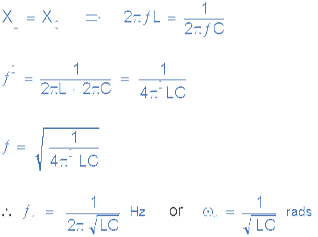
Notice that at resonance the parallel circuit produces the same equation as for the series resonance circuit. Therefore, it makes no difference if the inductor or capacitor are connected in parallel or series.
Also at resonance the parallel LC tank circuit acts like an open circuit with the circuit current being determined by the resistor, R only. So the total impedance of a parallel resonance circuit at resonance becomes just the value of the resistance in the circuit and Z = R as shown.
Thus at resonance, the impedance of the parallel circuit is at its maximum value and equal to the resistance of the circuit creating a circuit condition of high resistance and low current. Also at resonance, as the impedance of the circuit is now that of resistance only, the total circuit current, I will be “in-phase” with the supply voltage, VS.
We can change the circuit’s frequency response by changing the value of this resistance. Changing the value of R affects the amount of current that flows through the circuit at resonance, if both L and C remain constant. Then the impedance of the circuit at resonance Z = RMAX is called the “dynamic impedance” of the circuit.
Note that if the parallel circuits impedance is at its maximum at resonance then consequently, the circuits admittance must be at its minimum and one of the characteristics of a parallel resonance circuit is that admittance is very low limiting the circuits current. Unlike the series resonance circuit, the resistor in a parallel resonance circuit has a damping effect on the circuits bandwidth making the circuit less selective.
Also, since the circuit current is constant for any value of impedance, Z, the voltage across a parallel resonance circuit will have the same shape as the total impedance and for a parallel circuit the voltage waveform is generally taken from across the capacitor.
We now know that at the resonant frequency, ƒr the admittance of the circuit is at its minimum and is equal to the conductance, G given by 1/R because in a parallel resonance circuit the imaginary part of admittance, i.e. the susceptance, B is zero because BL = BC as shown.