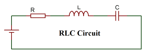
RLC Circuit
A RLC circuit as the name implies will consist of a Resistor, Capacitor and Inductor connected in series or parallel. The circuit forms an Oscillator circuit which is very commonly used in Radio receivers and televisions. It is also very commonly used as damper circuits in analog applications. The resonance property of a first order RLC circuit is discussed below
The RLC circuit is also called as series resonance circuit, oscillating circuit or a tuned circuit. These circuit has the ability to provide a resonant frequency signal as shown in the below image
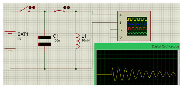
Here we have a capacitor C1 of 100u and an Inductor L1 of 10mH connected tin series through a switch. Since the wire that is connecting the C and L will have some internal resistance, it is assumed that a small amount of resistance is present due to the wire.
Initially, we keep the switch 2 as open and close the switch 1 to charge up the capacitor from the battery source (9V). Then once the capacitor is charged the switch 1 is opened and then the switch 2 is closed.
As soon as the switch is closed the charge stored in the capacitor will move towards the inductor and charge it up. Once the capacitor is fully dis-charged, the inductor will start discharging back into the capacitor this way charges will flow to and fro between the inductor and the capacitor. But since there will be some loss in charges during this process total charge will gradually decrease until it reaches zero as shown in the graph above.
The Resistors, Inductors and Capacitors may be normal and simple components but when they are combined to gather to form circuits like RC/RL and RLC circuit they exhibit complex behaviour which makes it suitable for a wide range of application. Few of them are listed below
§ Communication systems
§ Signal Processing
§ Voltage/Current magnification
§ Radio wave transmitters
§ RF amplifiers
§ Resonant LC circuit
§ Variable tunes circuits
§ Oscillator circuits
§ Filtering circuits