Transient response of RL circuit
After the introduction of the SMU ADALM1000 let’s continue with the fifth part of our series with some small, basic measurements.
Now let’s get started with the next experiment.
Objective:
The objective of this lab activity is to study the transient response of a series RL circuit and understand the time constant concept using pulse waveforms.
Background:
This lab activity is similar to another of our lab activities, Activity 4: Transient Response of an RC Circuit, except that the capacitor is replaced by an inductor. In this experiment, you will apply a square waveform to the RL circuit to analyze the transient response of the circuit. The pulse width relative to the circuit’s time constant determines how it is affected by the RL circuit.
Time Constant (): A measure of time required for certain changes in voltages and currents in RC and RL circuits. Generally, when the elapsed time exceeds five time constants () after switching has occurred, the currents and voltages have reached their final value, which is also called the steady-state response.
The time constant of an RL circuit is the equivalent inductance divided by the Thévenin resistance as viewed from the terminals of the equivalent inductor.

A pulse is a voltage or current that changes from one level to another and back again. If a waveform’s high time equals its low time, it is called a square wave. The length of each cycle of a pulse train is its period (). The pulse width () of an ideal square wave is equal to half the time period.
The relation between pulse width and frequency for the square wave is given by: . 
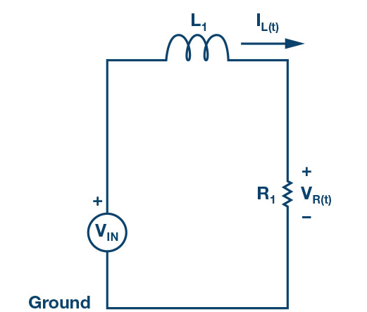
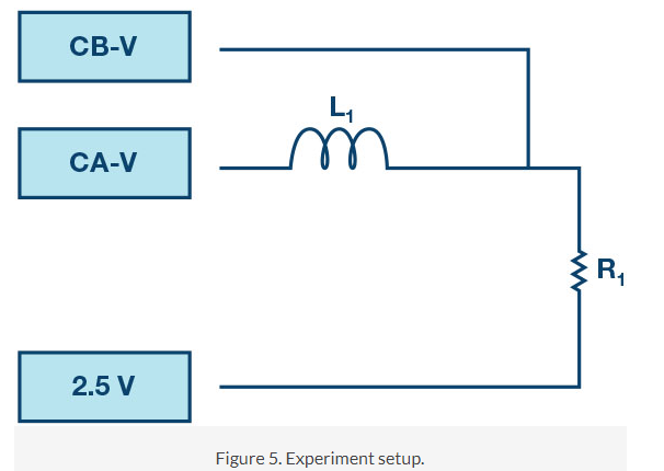
Figure 2. Series RL circuit.
Calculate the applied frequency using Equation 2 for
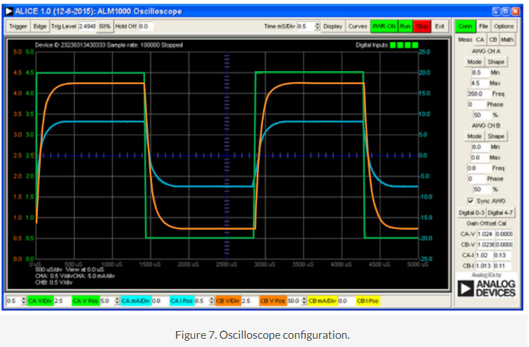
Figure 7. Oscilloscope configuration.