Reciprocity Theorem
Reciprocity Theorem states that – In any branch of a network or circuit, the current due to a single source of voltage (V) in the network is equal to the current through that branch in which the source was originally placed when the source is again put in the branch in which the current was originally obtained. This theorem is used in the bilateral linear network which consists of bilateral components.
In simple words, we can state the reciprocity theorem as when the places of voltage and current source in any network are interchanged the amount or magnitude of current and voltage flowing in the circuit remains the same.
This theorem is used for solving many DC and AC network which have many applications in electromagnetism electronics. These circuits do not have any time-varying element.
Explanation of Reciprocity Theorem
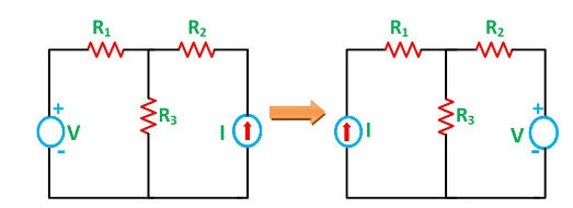
The location of the voltage source and the current source may be interchanged without a change in current. However, the polarity of the voltage source should be identical with the direction of the branch current in each position.
The Reciprocity Theorem is explained with the help of the circuit diagram shown below

The various resistances R1, R2, R3 is connected in the circuit diagram above with a voltage source (V) and a current source (I). It is clear from the figure above that the voltage source and current sources are interchanged for solving the network with the help of Reciprocity Theorem.
The limitation of this theorem is that it is applicable only to single-source networks and not in the multi-source network. The network where reciprocity theorem is applied should be linear and consist of resistors, inductors, capacitors and coupled circuits. The circuit should not have any time-varying elements.
Steps for Solving a Network Utilizing Reciprocity Theorem
Step 1 – Firstly, select the branches between which reciprocity has to be established.
Step 2 – The current in the branch is obtained using any conventional network analysis method.
Step 3 – The voltage source is interchanged between the branch which is selected.
Step 4 – The current in the branch where the voltage source was existing earlier is calculated.
Step 5 – Now, it is seen that the current obtained in the previous connection, i.e., in step 2 and the current which is calculated when the source is interchanged, i.e., in step 4 are identical to each other.