Potential difference and resistance
For a continuous current to flow between two points in a circuit a potential difference (p.d.) or voltage, V, is required between them; a complete conducting path is necessary to and from the source of electrical energy. The unit of p.d. is the volt, V
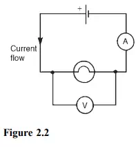
Figure 2.2 shows a cell connected across a filament lamp. Current flow, by convention, is considered as flowing from the positive terminal of the cell, around the circuit to the negative terminal.
The flow of electric current is subject to friction. This friction, or opposition, is called resistance R and is the property of a conductor that limits current. The unit of resistance is the ohm; 1 ohm is defined as the resistance which will have a current of 1 ampere flowing through it when 1 volt is connected across it, i.e
![]()
Basic electrical measuring instruments
An ammeter is an instrument used to measure current and must be connected in series with the circuit. Figure 2.2 shows an ammeter connected in series with the lamp to measure the current flowing through it. Since all the current in the circuit passes through the ammeter it must have a very low resistance.
A voltmeter is an instrument used to measure p.d. and must be connected in parallel with the part of the circuit whose p.d. is required. In Figure 2.2, a voltmeter is connected in parallel with the lamp to measure the p.d. across it. To avoid a significant current flowing through it a voltmeter must have a very high resistance.
An ohmmeter is an instrument for measuring resistance.
A multimeter, or universal instrument, may be used to measure voltage, current and resistance. An ‘Avometer’ is a typical example. The cathode ray oscilloscope (CRO) may be used to observe waveforms and to measure voltages and currents. The display of a CRO involves a spot of light moving across a screen. The amount by which the spot is deflected from its initial position depends on the p.d. applied to the terminals of the CRO and the range selected. The displacement is calibrated in ‘volts per cm’. For example, if the spot is deflected 3 cm and the volts/cm switch is on 10 V/cm then the magnitude of the p.d. is 3 cm ð 10 V/cm, i.e. 30 V
Linear and non-linear devices
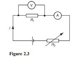
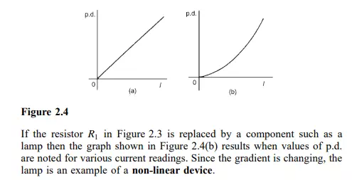
Figure 2.3 shows a circuit in which current I can be varied by the variable resistor R2. For various settings of R2, the current flowing in resistor R1, displayed on the ammeter, and the p.d. across R1, displayed on the voltmeter, are noted and a graph is plotted of p.d. against current. The result is shown in Figure 2.4(a) where the straight line graph passing through the origin indicates that current is directly proportional to the p.d. Since the gradient i.e. (p.d./current) is constant, resistance R1 is constant. A resistor is thus an example of a linear device.
Ohm’s law
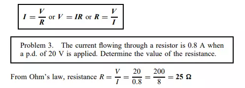
Ohm’s law states that the current I flowing in a circuit is directly proportional to the applied voltage V and inversely proportional to the resistance R, provided the temperature remains constant. Thus,
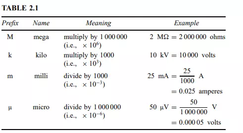
Multiples and sub-multiples
Currents, voltages and resistances can often be very large or very small. Thus multiples and sub-multiples of units are often used, as stated in chapter 1. The most common ones, with an example of each, are listed in Table 2.1