Adders
Introduction
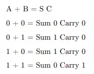
When adding one number A with another number B the operation will produce a Sum S and a Carry C. The Operation of an adder is Shown below.
Digital Adder
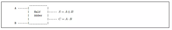
Half adder
If there are two binary number A and B . The operation of adding two numbers can be shown below
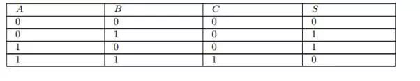
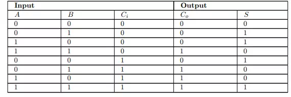
The operation of Half Adder can be summarized in the Truth Table below
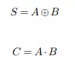
From above, In term of logic gate XOR will produce a sum of two input . logic gate AND produce carry
Half Adder can constructed from AND gate and XOR gate as shown below
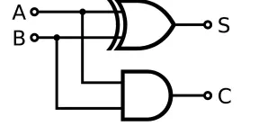
Half adder circuit diagram
Full adder
A full adder is a logical circuit that performs an addition operation on three one-bit binary numbers. The full adder produces a sum of the two inputs and carry value. It can be combined with other full adders (see below) or work on its own.
![]()
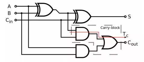
Full adder circuit diagram
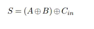
Inputs: {A, B, Carry In} → Outputs: {Sum, Carryout}
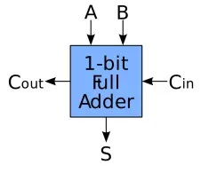
Schematic symbol for a 1-bit full adder
Note that the final OR gate before the carry-out output may be replaced by an XOR gate without altering the resulting logic. This is because the only difference between OR and XOR gates occurs when both inputs are 1; for the adder shown here, this is never possible. Using only two types of gates is convenient if one desires to implement the adder directly using common IC chips.
A full adder can be constructed from two half adders by connecting A and B to the input of one half adder, connecting the sum from that to an input to the second adder, connecting Ci to the other input and OR the two carry outputs. Equivalently, S could be made the three-bit XOR of A , B , and Ci , and Co could be made the three-bit majority function1 of A , B , and Ci .