Flip Flops
A flip-flop is a device very like a latch1 in that it is a bistable multi vibrator, having two states and a feedback path that allows it to store a bit of information. The difference between a latch and a flip-flop is that a latch is asynchronous, and the outputs can change as soon as the inputs do (or at least after a small propagation delay). A flip-flop, on the other hand, is edge-triggered and only changes state when a control signal goes from high to low or low to high. This distinction is relatively recent and is not formal, with many authorities still referring to flip-flops as latches and vice versa, but it is a helpful distinction to make for the sake of clarity.
There are several different types of flip-flop each with its own uses and peculiarities. The four main types of flip-flop are : SR, JK, D, and T.
RS Flip Flop
An SR latch (Set/Reset) is an asynchronous device: it works independently of control signals and relies only on the state of the S and R inputs. In the image we can see that an SR flip-flop can be created with two NOR gates that have a cross-feedback loop. SR latches can also be made from NAND gates, but the inputs are swapped and negated. In this case, it is sometimes called an SR pt latch .
An SR (Set/Reset) flip-flop is perhaps the simplest flip-flop, and is very similar to the SR latch2 , other than for the fact that it only transitions on clock edges. While as theoretically valid as any flip-flop, synchronous edge-triggered SR flip-flops are extremely uncommon because they retain the illegal state when both S and R are asserted. Generally when people refer to SR flip-flops, they mean SR latches.
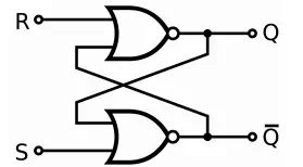
An SR latch made from two NOR gates.
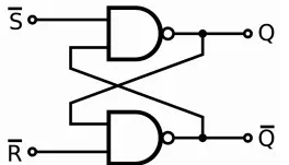
An SR pt latch made from two NAND gates
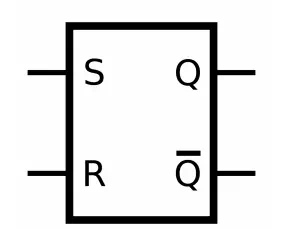
Circuit symbol for an SR latch.
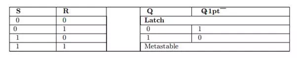
When a high is applied to the Set line of an SR latch, the Q output goes high (and Q +1pt low). The feedback mechanism, however, means that the Q output will remain high, even when the S input goes low again. This is how the latch serves as a memory device. Conversely, a high input on the Reset line will drive the Q output low (and Q +1pt high), effectively resetting the latch’s ”memory”. When both inputs are low, the latch ”latches” – it remains in its previously set or reset state.
When both inputs are high at once, however, there is a problem: it is being told to simultaneously produce a high Q and a low Q . This produces a ”race condition” within the circuit - whichever flip flop succeeds in changing first will feedback to the other and assert itself. Ideally, both gates are identical, and this is ”metastable”, and the device will be in an undefined state for an indefinite period. In real life, due to manufacturing methods, one gate will always win, but it’s impossible to tell which it will be for a particular device from an assembly line. The state of S = R = 1 is therefore ”illegal” and should never be entered.
When the device is powered up, a similar condition occurs, because both outputs, Q and Q +1pt , are low. Again, the device will quickly exit the metastable state due to differences between the two gates, but it’s impossible to predict which of Q and Q+1pt will end up high. To avoid spurious actions, you should always set SR flip-flops to a known initial state before using them - you must not assume that they will initialise to a low state.