Impedance
Definition
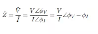
Impedance, Z˜, is the quantity that relates voltage and current in the frequency domain. (The tilde indicates a phasor1 . An over score or arrow may also be used.)
In rectangular form,
![]()
NOTE: ω = 2 π f
where f is the frequency in cycles per second (f=50 or 60 Hertz usually, depending on the country concerned. Aircraft systems often use 400 Hertz.)
Reactance
Reactance (symbol X) is the resistance to current flow of a circuit element that can store energy (i.e. a capacitor or an inductor), and is measured in ohms.
The reactance of an inductor of inductance L (in Henries), through which an alternating current of angular frequency w flows is given by:
![]()
The reactance of a capacitor of capacitance C (in Farads) is given similarly:
![]()
The two formulae for inductive reactance and capacitive reactance create interesting counterpoints. Notice that for inductive reactance, as the frequency of the AC increases, so does the reactance. Hence, higher frequencies result in lower current. The opposite is true of capacitive reactance: The higher the frequency of AC, the less reactance a capacitor will present.
Similarly, a more inductive inductor will present more reactance, while a capacitor with more capacitance will yield less reactance.
Resistors
Resistors have zero reactance, since they do not store energy, so their impedance is simply

Capacitors
Capacitors have zero resistance, but do have reactance. it is stored in the power of a circuit or it can be also stored in a motor running off an AC current. Their impedance is
![]()
where C is the capacitance in farads. The reactance of one microfarad at 50 Hz is -3183 ohms, and at 60 Hz it is -2653 ohms. In much more basic terms storing energy would be equivalent to a battery the power source is active and stays in this manner without any loss of power, this is what is regarded as a means for reversing electricity in the process of keeping that current.
Inductors
Like capacitors, inductors have zero resistance, but have reactance. Their impedance is
![]()
where L is the inductance in henries. The reactance of one henry at 50 Hz is 314 ohms, and at 60 Hz it is 377 ohms
Circuit Analysis Using Impedance
Analysis in the frequency domain proceeds exactly like DC analysis, but all currents and voltages are now phasors (and so have an angle). Impedance is treated exactly like a resistance, but is also a phasor (has an imaginary component/angle depending on the representation.) (In the case that a circuit contains sources with different frequencies, the principle of superposition2 must be applied.) Note that this analysis only applies to the steady state3 response of circuits. For circuits with transient characteristics, circuits must be analysed in the Laplace domain, also known as s-domain analysis.