Auto Transformer
This is type of transformer which is mostly seen in our electrical laboratories. This auto transformer is an improved version of the original transformer. A single winding is taken to which both the sides are connected to power and the ground. Another variable tapping is made by whose movement secondary of the transformer is formed.
The following figure shows the circuit of an auto-transformer.
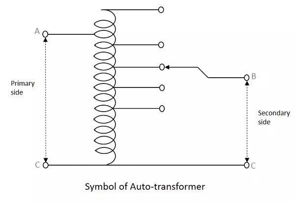
As shown in the figure, a single winding provides both primary and secondary in a transformer. Various tapping of secondary winding are drawn to select various voltage levels at the secondary side.
The primary winding as shown above is from A to C and the secondary winding is from B to C whereas the variable arm B is varied to get the required voltage levels. A practical auto transformer looks like the figure below.
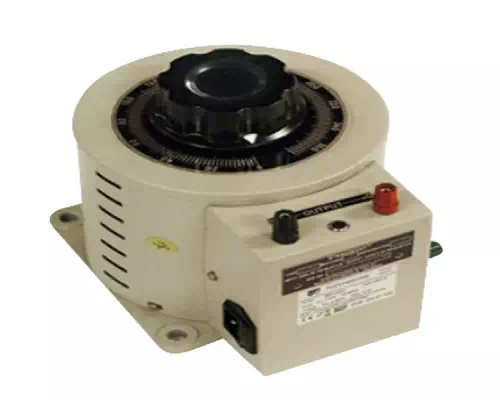
By rotating the shaft above, the secondary voltage is adjusted to different voltage levels. If the voltage applied across the points A and C is V1, then the voltage per turn in this winding will be
Voltageperturn=V1N1Voltageperturn=V1N1
Now, the voltage across the points B and C will be
V2=V1N1×N2V2=V1N1×N2
V2V1=N2N1=constant(sayK)V2V1=N2N1=constant(sayK)
This constant is nothing but the turns ratio or voltage ratio of the auto transformer.