Transformers
According to the principle of Electromagnetic Induction, we have already learnt that, a varying flux can induce an EMF in a coil. By the principle of Mutual induction, when another coil is brought beside such coil, the flux induces EMF into the second coil.
Now, the coil which has the varying flux is called as the Primary Coil and the coil into which EMF is induced is called as the Secondary Coil, while the two coils together makes a unit called as a Transformer.
Transformer
A transformer has a primary coil to which input is given and a secondary coil from which the output is collected. Both of these coils are wound on a core material. Usually an insulator forms the Core of the transformer.
The following figure shows a practical transformer.
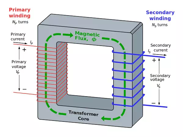
From the above figure, it is evident that few notations are common. Let us try to have a note of them. They are −
· Np = Number of turns in the primary winding
· Ns = Number of turns in the secondary winding
· Ip = Current flowing in the primary of the transformer
· Is = Current flowing in the secondary of the transformer
· Vp = Voltage across the primary of the transformer
· Vs = Voltage across the secondary of the transformer
· Φ = Magnetic flux present around the core of the transformer.
Transformer in a Circuit
The following figure shows how a transformer is represented in a circuit. The primary winding, the secondary winding and the core of the transformer are also represented in the following figure.
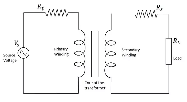
Hence, when a transformer is connected in a circuit, the input supply is given to the primary coil so that it produces varying magnetic flux with this power supply and that flux is induced into the secondary coil of the transformer, which produces the varying EMF of the varying flux. As the flux should be varying, for the transfer of EMF from primary to secondary, a transformer always works on alternating current AC.