Mutual Inductance
As the current carrying coil produces some magnetic field around it, if another coil is brought near this coil, such that it is in the magnetic flux region of the primary, then the varying magnetic flux induces an EMF in the second coil. If this first coil is called as Primary coil, the second one can be called as a Secondary coil.
When the EMF is induced in the secondary coil due to the varying magnetic field of the primary coil, then such phenomenon is called as the Mutual Inductance.
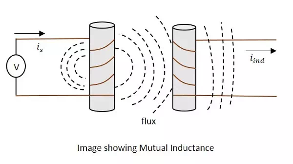
The current is in the figure indicate the source current while iind indicates the induced current. The flux represents the magnetic flux created around the coil. This spreads to the secondary coil also.
With the application of voltage, the current is flows and flux gets created. When the current is varies, the flux gets varied producing iind in the secondary coil, due to the Mutual inductance property.
The change took place like this.
VpIp→B→VsIsVpIp→B→VsIs
Where,
· Vp ip Indicate the Voltage and current in Primary coil respectively
· B Indicates Magnetic flux
· Vs is Indicate the Voltage and current in Secondary coil respectively
Mutual inductance M of the two circuits describes the amount of the voltage in the secondary induced by the changes in the current of the primary.
V(Secondary)=−MΔIΔtV(Secondary)=−MΔIΔt
Where ΔIΔtΔIΔt the rate of change of current with time and M is the co-efficient of Mutual inductance. The minus sign indicates the direction of current being opposite to the source.
Units −
The units of Mutual inductance is
volt=Mampssecvolt=Mampssec
(From the above equation)
M=volt.secampM=volt.secamp
=Henry(H)=Henry(H)
Depending upon the number of turns of the primary and the secondary coils, the magnetic flux linkage and the amount of induced EMF varies. The number of turns in primary is denoted by N1 and secondary by N2. The co-efficient of coupling is the term that specifies the mutual inductance of the two coils.