Common Collector (CC) Configuration
The name itself implies that the Collector terminal is taken as common terminal for both input and output of the transistor. The common collector connection for both NPN and PNP transistors is as shown in the following figure.
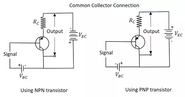
Just as in CB and CE configurations, the emitter junction is forward biased and the collector junction is reverse biased. The flow of electrons is controlled in the same manner. The input current is the base current IB and the output current is the emitter current IE here.
Current Amplification Factor (γ)
The ratio of change in emitter current (ΔIEΔIE) to the change in base current (ΔIBΔIB) is known as Current Amplification factor in common collector (CC) configuration. It is denoted by γ.
γ=ΔIEΔIBγ=ΔIEΔIB
· The current gain in CC configuration is same as in CE configuration.
· The voltage gain in CC configuration is always less than 1.
Relation between γ and α
Let us try to draw some relation between γ and α
γ=ΔIEΔIBγ=ΔIEΔIB
α=ΔICΔIEα=ΔICΔIE
IE=IB+ICIE=IB+IC
ΔIE=ΔIB+ΔICΔIE=ΔIB+ΔIC
ΔIB=ΔIE−ΔICΔIB=ΔIE−ΔIC
Substituting the value of IB, we get
γ=ΔIEΔIE−ΔICγ=ΔIEΔIE−ΔIC
Dividing by ΔIEΔIE
γ=ΔIEΔIEΔIEΔIE−ΔICΔIEγ=ΔIEΔIEΔIEΔIE−ΔICΔIE
11−α11−α
γ=11−αγ=11−α
Expression for collector current
We know
IC=αIE+ICBOIC=αIE+ICBO
IE=IB+IC=IB+(αIE+ICBO)IE=IB+IC=IB+(αIE+ICBO)
IE(1−α)=IB+ICBOIE(1−α)=IB+ICBO
IE=IB1−α+ICBO1−αIE=IB1−α+ICBO1−α
IC≅IE=(β+1)IB+(β+1)ICBOIC≅IE=(β+1)IB+(β+1)ICBO
The above is the expression for collector current.
Characteristics of CC Configuration
· This configuration provides current gain but no voltage gain.
· In CC configuration, the input resistance is high and the output resistance is low.
· The voltage gain provided by this circuit is less than 1.
· The sum of collector current and base current equals emitter current.
· The input and output signals are in phase.
· This configuration works as non-inverting amplifier output.
· This circuit is mostly used for impedance matching. That means, to drive a low impedance load from a high impedance source.