Working of JFET
One best example to understand the working of a JFET is to imagine the garden hose pipe. Suppose a garden hose is providing a water flow through it. If we squeeze the hose the water flow will be less and at a certain point if we squeeze it completely there will be zero water flow. JFET works exactly in that way. If we interchange the hose with a JFET and the water flow with a current and then construct the current-carrying channel, we could control the current flow.
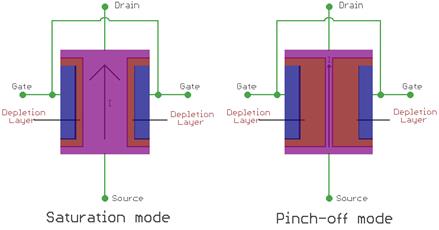
When there is no voltage across gate and source, the channel becomes a smooth path which is wide open for electrons to flow. But the reverse thing happens when a voltage is applied between gate and source in reverse polarity, that makes the P-N junction reversed biased and makes the channel narrower by increasing the depletion layer and could put the JFET in cut-off or pinch off region.
In the below image we can see the saturation mode and pinch off mode and we will be able to understand the depletion layer became wider and the current flow becomes less.
If we want to switch off a JFET we need to provide a negative gate to source voltage denoted as VGS for an N-type JFET. For a P-type JFET, we need to provide positive VGS.
JFET only works in the depletion mode, whereas MOSFETs have depletion mode and enhancement mode.
JFET Characteristics Curve
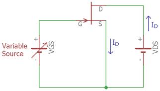
In the above image, a JFET is biased through a variable DC supply, which will control the VGS of a JFET. We also applied a voltage across the Drain and Source. Using the variable VGS, we can plot the I-V curve of a JFET.
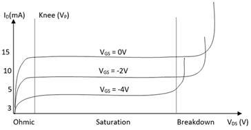
In the above I-V image, we can see three graphs, for three different values of VGS voltages, 0V, -2V and -4V. There are three different regions Ohmic, Saturation, and Breakdown region. During the Ohmic region, the JFET acts like a voltage controlled resistor, where the current flow is controlled by voltage applied to it. After that, the JFET gets into the saturation region where the curve is almost straight. That means the current flow is stable enough where the VDS would not interfere with the current flow. But when the VDS is much more than the tolerance, the JFET gets into the breakdown mode where the current flow is uncontrolled.
This IV curve is almost the same for the P channel JFET too, but there are few differences exist. The JFET will go into a cut-off mode when VGS and Pinch voltage or (VP) is same. Also as in the above curve, for N channel JFET the drain current increase when the VGS increase. But for the P-channel JFET the drain current decrease when the VGS increase.