
Types of JFET
Same like MOSFET it has two subtypes- N Channel JFET and P Channel JFET.
N channel JFET and P channel JFET schematic model are shown in the image above. The arrow denotes the types of JFET. The arrow showing to the gate denotes that the JFET is N-channel and on the other hand the arrow from the gate denotes P-channel JFET. This arrow also indicates the polarity of P-N junction, which is formed between the channel and the gate. Interestingly, an English mnemonic is this, that arrow of an N- Channel device indicates “Points in”.
The current flowing through the Drain and Source is dependable on the voltage applied to the Gate terminal. For the N channel JFET, the Gate voltage is negative and for the P channel JFET the Gate voltage is positive.
Construction of JFET
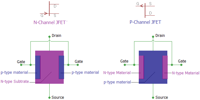
In the above image, we can see the basic construction of a JFET. The N-Channel JFET consists of P-type material in N-type substrate whereas N-type materials are used in the p-type substrate to form a P channel JFET.
JFET is constructed using the long channel of semiconductor material. Depending on the construction process, if the JFET contains a great number of positive charge carriers (refers as holes) is a P-type JFET, and if it has a large number of negative charge carriers (refers as electrons) is called N-type JFET.
In the long channel of semiconductor material, Ohmic contacts at each end are created to form the Source and Drain connections. A P-N junction is formed in one or both side of the channel.