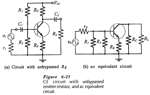
CE Circuit with Unbypassed Emitter Resistor
h-parameter Equivalent Circuit – When an CE Circuit with Unbypassed Emitter Resistor (RE) as shown in Fig. 6-25(a), it is also present in the ac equivalent circuit, [Fig. 6-25(b)].

RE must also be shown in the h-parameter circuit between the transistor emitter terminal and the circuit common input-output terminal, (Fig. 6-26). As with the previous h-parameter circuit, the current directions and voltage polarities shown are those that occur when the instantaneous input voltage is positive-going. The presence of RE without a bypass capacitor significantly affects the circuit input impedance and voltage gain.

An equation for the input impedance at the transistor base can be determined from υ1 and Ib. From Fig. 6-26,

Equation 6-20 gives the input impedance at the transistor base terminal. The circuit input impedance is again given by,

Examination of Eq. 6-20 shows that it is possible to very quickly estimate the input impedance at the transistor base in a CE Circuit with Unbypassed Emitter Resistor. For example, a circuit with RE = 1 kΩ and hfe = 100, has Zb ≈ 100 kΩ.
The output impedance at the transistor collector can be shown to be substantially increased (above 1 / hoe) by the presence of the CE Circuit with Unbypassed Emitter Resistor. Consequently, the circuit output impedance should be taken as,

From the derivation of the input impedance equation,

The voltage gain of a CE Circuit with Unbypassed Emitter Resistor can be quickly estimated using Eq. 6-22. For the circuit in Fig. 6-25(a), with RC = 4.7 kΩ, RE =1 kΩ, and RL ≫ RC, Aυ ≈ -4.7.

The most significant feature of the performance of a CE Circuit with Unbypassed Emitter Resistor is that its voltage gain is much lower than it would be normally. Its input impedance is also much higher than Zi for a CE circuit that has RE bypassed.