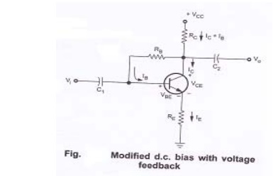
Modified collector to base bias circuit
To improve the level of stability, emitter resistance is connected in this circuit.
Base circuit:
Applying KVL to base circuit,
VCC – (IC + IB ) RC – IBRB – VBE – IERE = 0
IB = [VCC – VBE ] / [RB + (1+β) (RC + RE)]
IB = [VCC – VBE]/ [RB + β (RC + RE)]
Only difference between the equation for IB and that obtained for the fixed bias configuration is the term β (RC + RE).So feedback path results in a reflection of the resistance RC back to the input circuit.
In general,
IB = V’ / RB + β R’
Where V’ = VCC - VBE
R’ = 0 for fixed bias
R’ = RE for emitter bias
R’ = RC for collector to base bias
R’ = RC + RE for collector to base bias with RE
Collector circuit:
Applying KVL to collector circuit,
VCC – (IC+IB) RC – VCE – IERE = 0
VCE = VCC – I E (RC+RE)
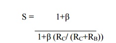
Stability factor S for collector to base bias circuit:
VCC = IC RC – IB(RB+RC) + VBE
When ICBO, IB and IC changes with no effect on VCC and VBE, the equation becomes,
S = [1+β ] /1+β (RC/ (RC+RB))
Collector to base bias circuit is having lesser stability factor than for fixed bias circuit. So this circuit provides better stability than fixed bias circuit.
Problem 1:
Locate the operating point of the given circuit with VCC = 15V, hfe = 200.
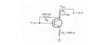
Solution:
IBQ = [VCC – VBE] / [RB+ (1+β) (RC+RE)]
= 15-0.7 / 630*103 + (1+200) (4.7*103+680)
ICQ = β IBQ = 200*8.356*10-6 = 1.6712mA
IEQ = ICQ + IBQ = 1.6712*10-3 + 8.356*10-6 = 1.68mA
VCEQ = VCC – IE (RC+RE)
= 15-1.68*10-3 (4.7*103 + 680)
5.96V