cut off frequency
What is Cutoff Frequency?
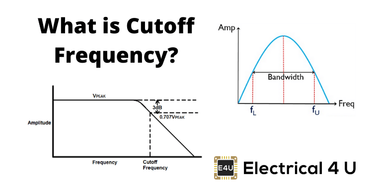
Cutoff frequency (also known as corner frequency, or break frequency) is defined as a boundary in a system’s frequency response at which energy flowing through the system begins to be attenuated (reflected or reduced) rather than passing through.
The cutoff frequency or corner frequency in electronics is the frequency either above or below which the power output of a circuit, such as a line, amplifier, or electronic filter (e.g. a high pass filter) has fallen to a given proportion of the power in the passband.
Most frequently this proportion is one half the passband power, also referred to as the 3 dB point since a fall of 3 dB corresponds approximately to half power. As a voltage ratio, this is a fall to approximately 0.707.
For any filtering circuits such as RC circuits, the cutoff frequency is a very important characteristic. At this point, the amount of attenuation due to the filter starts to increase swiftly.
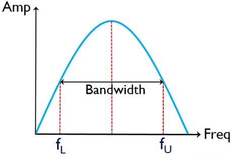
To indicate how long the amplifier gain can remain constant to frequency, we need to define a range of frequencies. Along with that range, the gain should not deviate more than 70.7% of the maximum gain that has been defined as a reference at mid-frequency. In the below-shown curve, f1 and f2 indicate lower cut off and upper cut off frequencies.
Bandwidth
In signal processing, bandwidth is defined as the difference between upper cutoff frequency and low cutoff frequency. The frequency f2 lies along with a high-frequency range and f1 in the low-frequency range. We can also name these two frequencies as Half – Power frequencies since voltage gain drops to 70.7 % of the maximum value.
This represents the power level of one – half of the power at reference frequency in the mid-range frequency. Since the change is not noticeable, the audio amplifier has a flat response from f1 to f2.
Cutoff Frequency Equation
The formula for cutoff frequency (corner frequency) is
![]()
where R and C are the values of Resistance and Capacitance. For a simple RC low pass filter, cut-off (3dB point) is defined as when the resistance is the same magnitude as the capacitive reactance
Decibel Unit
Gain is usually expressed in decibels. Decibel unit arises from the logarithmic response of the human ear to intensity of sound. Hence decibel is given as logarithmic measurement of the ratio of one power to another, it can also be expressed as a ratio of one voltage to another.
Generally, voltage output or voltage gain of an amplifier is
expressed in decibels (dB) which is given by Voltage gain in dB is ![]() .
.
The power gain of the amplifier is expressed in decibels (dB)
which is given by power gain in dB is ![]()
When Av is greater than one, it is said that dB gain is positive. It represents the amplification. When Av is less than one, dB is negative. It represents the attenuation.
In amplifiers under few circumstances, value of gain may be assigned with 0 dB reference. In such situation it means that reference gain is used as reference which is used to compare other values of gain.
Amplifiers show a maximum gain in mid-frequency range and reduced gain in the low-frequency range. Maximum gain is called the mid-frequency range with a value of 0 dB. When the gain value is below the mid-frequency range, it is expressed as a negative dB value.
How to Find Cutoff Frequency
There are many methods by which cutoff frequency can be calculated.
Cutoff Frequency from Transfer Function
Analysis of a circuit with an altering frequency of sinusoidal sources is termed as the frequency response of a circuit. The transfer function of a circuit is defined as the ratio of the output voltage to input voltage in s domain.
![]()
When using a sinusoidal source, the transfer function will be
given as the magnitude and phase of the output voltage to the magnitude and
phase of input voltage in a circuit. In such a case, ![]() will be used instead of s.
will be used instead of s.
![]()
For example, consider the transfer function
![]()
To obtain the corner frequency from the above equation, H(s) can be replaced as
(1) ![]()
(2) ![]()
So, from this equation, the corner frequency is calculated as ![]() and
and ![]() . In order to choose the range
of frequencies, we must consider the values of corner frequency.
. In order to choose the range
of frequencies, we must consider the values of corner frequency.