Bias Compensation
So far we have seen different stabilization techniques. The stabilization occurs due to negative feedback action. The negative feedback, although improves the stability of operating point, it reduces the gain of the amplifier. As the gain of the amplifier is a very important consideration, some compensation techniques are used to maintain excellent bias and thermal stabilization. Let us now go through such bias compensation techniques.
Diode Compensation for Instability
These are the circuits that implement compensation techniques using diodes to deal with biasing instability. The stabilization techniques refer to the use of resistive biasing circuits which permit IB to vary so as to keep IC relatively constant.
There are two types of diode compensation methods. They are −
- Diode compensation for instability due to VBE variation
- Diode compensation for instability due to ICO variation
Let us understand these two compensation methods in detail.
Diode Compensation for Instability due to VBE Variation
In a Silicon transistor, the changes in the value of VBE results in the changes in IC. A diode can be employed in the emitter circuit in order to compensate the variations in VBE or ICO. As the diode and transistor used are of same material, the voltage VD across the diode has same temperature coefficient as VBE of the transistor.
The following figure shows self-bias with stabilization and compensation.
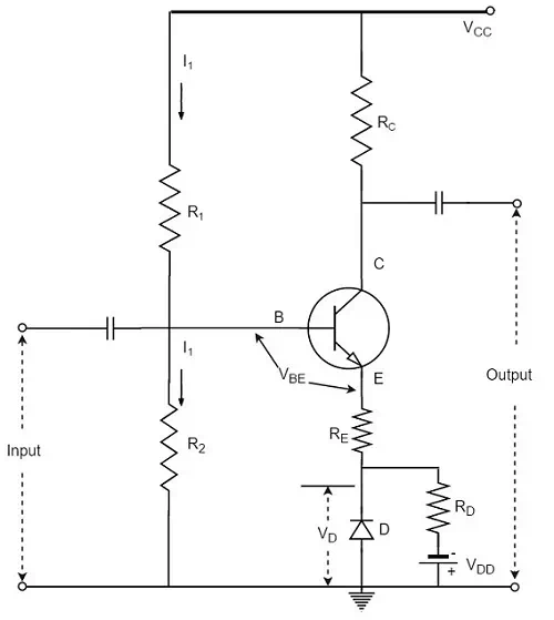
The diode D is forward biased by the source VDD and the resistor RD. The variation in VBE with temperature is same as the variation in VD with temperature, hence the quantity (VBE – VD) remains constant. So the current IC remains constant in spite of the variation in VBE.
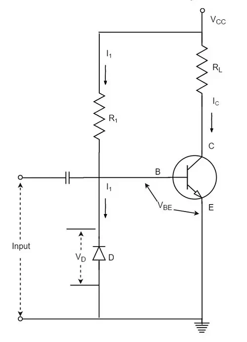
Diode Compensation for Instability due to ICO Variation
The following figure shows the circuit diagram of a transistor amplifier with diode D used for compensation of variation in ICO.
The metal sheet that helps to dissipate the additional heat from the transistor is known as the heat sink. The ability of a heat sink depends upon its material, volume, area, shape, contact between case and sink, and the movement of air around the sink.
The heat sink is selected after considering all these factors. The image shows a power transistor with a heat sink.
A tiny transistor in the above image is fixed to a larger metal sheet in order to dissipate its heat, so that the transistor doesn’t get damaged.
Thermal Runaway
The use of heat sink avoids the problem of Thermal Runaway. It is a situation where an increase in temperature leads to the condition that further increase in temperature, leads to the destruction of the device itself. This is a kind of uncontrollable positive feedback.
Heat sink is not the only consideration; other factors such as operating point, ambient temperature, and the type of transistor used can also cause thermal runaway.