Transformer Coupled Class A Power Amplifier
The class A power amplifier as discussed in the previous chapter, is the circuit in which the output current flows for the entire cycle of the AC input supply. We also have learnt about the disadvantages it has such as low output power and efficiency. In order to minimize those effects, the transformer coupled class A power amplifier has been introduced.
The construction of class A power amplifier can be understood with the help of below figure. This is similar to the normal amplifier circuit but connected with a transformer in the collector load.
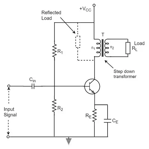
Here R1 and R2 provide potential divider arrangement. The resistor Re provides stabilization, Ce is the bypass capacitor and Re to prevent a.c. voltage. The transformer used here is a step-down transformer. The high impedance primary of the transformer is connected to the high impedance collector circuit. The low impedance secondary is connected to the load (generally loud speaker).
Transformer Action
The transformer used in the collector circuit is for impedance matching. RL is the load connected in the secondary of a transformer. RL’ is the reflected load in the primary of the transformer.
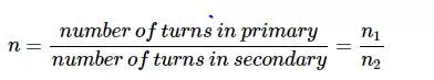
The number of turns in the primary are n1 and the secondary are n2. Let V1and V2 be the primary and secondary voltages and I1 and I2 be the primary and secondary currents respectively. The below figure shows the transformer clearly.
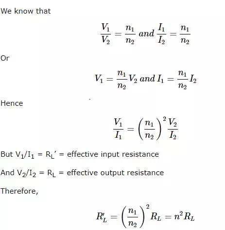
Where
A power amplifier may be matched by taking proper turn ratio in step down transformer.
Circuit Operation
If the peak value of the collector current due to signal is equal to zero signal collector current, then the maximum a.c. power output is obtained. So, in order to achieve complete amplification, the operating point should lie at the center of the load line.
The operating point obviously varies when the signal is applied. The collector voltage varies in opposite phase to the collector current. The variation of collector voltage appears across the primary of the transformer.
Circuit Analysis
The power loss in the primary is assumed to be negligible, as its resistance is very small.
The input power under dc condition will be
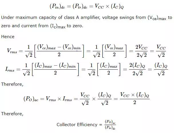
Or,
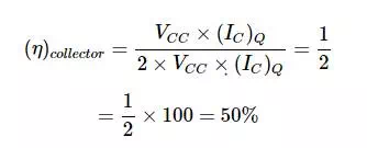
The efficiency of a class A power amplifier is nearly than 30% whereas it has got improved to 50% by using the transformer coupled class A power amplifier.
Advantages
The advantages of transformer coupled class A power amplifier are as follows.
- No loss of signal power in the base or collector resistors.
- Excellent impedance matching is achieved.
- Gain is high.
- DC isolation is provided.
Disadvantages
The disadvantages of transformer coupled class A power amplifier are as follows.
- Low frequency signals are less amplified comparatively.
- Hum noise is introduced by transformers.
- Transformers are bulky and costly.
- Poor frequency response.
Applications
The applications of transformer coupled class A power amplifier are as follows.
· This circuit is where impedance matching is the main criterion.
· These are used as driver amplifiers and sometimes as output amplifiers.