THE VALUES LIMIT FOR A TRANSISTOR
Like any component, the transistor can function only between certain limiting values of the electric quantities which are dependant for him.
These values limit are dependant on the type of the transistor, its dimensions, its constitution…
For example, a low-size transistor will dissipate less power than another of more important size.
For each type of transistor, the manufacturer provides limiting values which should not be exceeded under the normal conditions of use. In the contrary case, the transistor can be irremediably damaged, or all at least to cause an abnormal operation.
The values limit generally provided by the manufacturers are as follows :
Other limiting values relating to the base and the transmitter can be provided.
The maximum value of the collector current
This value is given so that the transistor functions correctly and so that the junction cannot be damaged.
In figure 15, this value limits IC max is represented by a horizontal line in dotted line. In this case, IC max = 10 mA.
The point of operation of the transistor must be located in lower part of this dotted line.
According to the value of resistance RC, two situations are to be considered.
All the points of operation are thus located in lower part of this dotted line.
The maximum value of the tension of collector
During the examination of the diode with junction, you saw that there was opposite a tension known as “tension of breakdown” beyond which the diode was damaged. However, in the transistor, the junction collector-bases is equivalent to a polarized diode in reverse.
There is thus a maximum tension between the collector and the base of the transistor not to be exceeded. In other words, there is a max. tension VCE.
On figure 16, tension VCE max is indicated by the tear line.
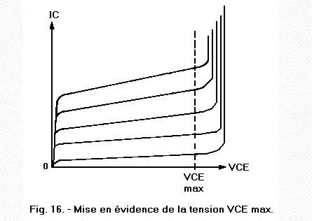
The point of operation of the transistor must be located on the left of this dotted line.
If tension VCE exceeds notably the value of VCE max, IC become very important and the transistor is likely to be destroyed.
The maximum value of the power of dissipation of the collector
The transistor absorbs a power equal to the product of tension VCE by current IC.
We have the relation :
PC = VCE x IC
PC will be expressed in mW, if VCE is in volts and IC in mA.
This power absorptive by the transistor corresponds to a consumption of electric power.
This electric power is converted in the transistor into calorific energy by Joule effect. Consequently, there is heating of the transistor; in particular the temperature of the junction increases.
However, as the temperature of junction cannot exceed a certain value, it is necessary to limit the power dissipated by the transistor.
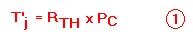
The increase in the temperature of the junction can result from the following formula :
The Rth coefficient is expressed in °C / W and indicates the increase in temperature of the junction in °C for a dissipation of power of one Watt.
Let us take an example :
Rth = 400°C / W, VCE = 5 volts, IC = 3 mA,
PC = 5 x 3 = 15 mW
From where | T'j = 400 x 0,015 = 6° C |
The temperature of the junction increases 6° C.
To calculate the temperature of the junction, the relation should be applied :
Tj = Ta + T'j | (2) |
By taking again the example above with Ta = 25° C, we have :
Tj = 25 + 6 = 31° C
The acceptable maximum temperature on the level of the junction is between 150° C and 200° C for a transistor at silicon.
The temperature of the Tj junction depends on the ambient temperature Ta and the increase in temperature T'j which is related to PC. Consequently, maximum power acceptable PC maxdepends not only on the type of transistor but also on Ta.
A manufacturer thus indicates a value of PC max for a fixed temperature Ta.
Generally, the values of Rth and Tj max are provided by the manufacturer.
Under these conditions, one can calculate PC max starting from the relations (1) and (2) :

If one knows the values of Tj max, Ta and Rth, it is easy to calculate max. PC.
It is interesting to see how the knowledge of PC max limits the zone of use of the network of characteristics.
Since the value of PC max is known, it is easy to plot a curve representing the relation :
VCE x IC = PC max
Figure 17 represents an example with three curves relating to three values of PC max (400 mW, 200 mW and 100 mW).
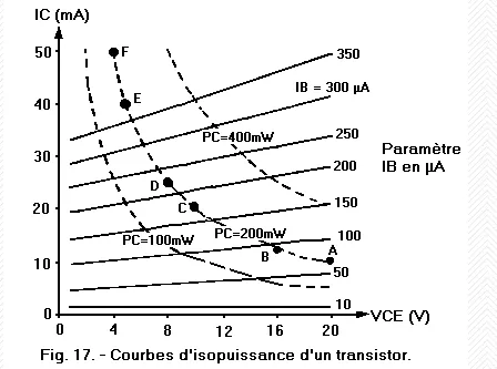
These curves are called curved of isopuissance, because for all the points of operation located on a curve, the power dissipated by the transistor is identical.
Generally, one defers on the network of characteristics the curve of isopuissance, IC max and VCE max as that appears on figure 18.
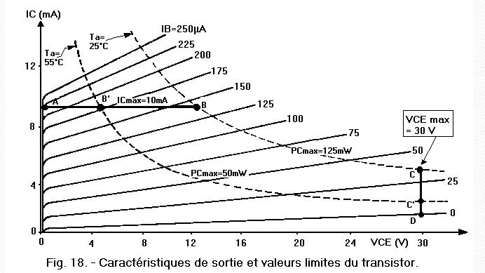
Any point of operation will have to be located in the zone ranging between the two axes of the reference mark, the two segments of right-hand side representing IC max and VCE max and the curve of isopuissance corresponding to the transistor used.
For an ambient temperature of 25° C, PC max is equal to 125 mW and consequently, the useful zone is delimited by items 0, A, B, C and D.
This useful zone decrease quickly if the ambient temperature increases: If Ta = 55° C, PC max = 50 mW ; in this case, the useful surface area is delimited by items 0, A, B', C' and D.