PIECEWISE LINEAR ANALYSIS
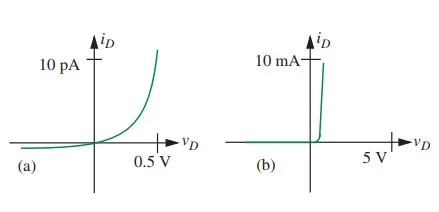
In the third of the four major methods of analysis for networks containing nonlinear elements, we represent the nonlinear v i characteristics of each nonlinear element by a succession of straight-line segments, then make calculations within each straight-line segment using the linear analysis tools already developed. This is called piecewise linear analysis. We will first illustrate piecewise linear analysis by using as an example a very simple piecewise linear model for the diode called the ideal diode model. First, let us develop a simple piecewise linear model for the diode, and then use the piecewise linear method to analyze the circuit in Figure 4.16. As can be seen from Figure a, the essential property of a diode is that for an applied positive voltage vD in excess of 0.6 volts, large amounts of current flow, whereas for negative voltages very small currents flow.
v–i characteristics of a silicon diode plotted using different scales.
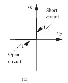
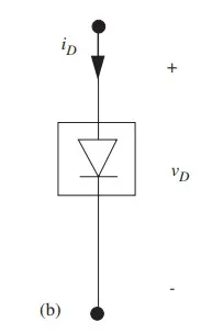
Figure b draws the v-i curve using a larger scale and highlights this dichotomy. The crudest approximation that preserves this dichotomy is the characteristic shown in Figure 4.23a: two linear segments intersecting at the origin, one of zero slope, indicating the behavior of an open circuit, the other infinite, indicating a short circuit. The abstraction is of sufficient use that we give it a special symbol, as shown in Figure 4.23b. This is yet another primitive in our vocabulary, called an ideal diode.
The behavior of this piecewise linear model can be summarized in two statements, one for each of the segments:
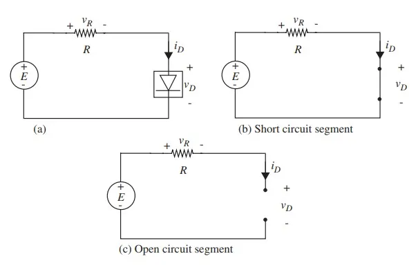
We now use the diode model comprising two straight-line segments to illustrate the piecewise linear analysis method applied to the circuit in Figure (also shown in Figure a). In particular, we will determine the voltage vR across the resistor and the current iD through the resistor for two values of the input voltage, E = 3 V and E = −5 V, and given that R = 500 Ω.
The piecewise linear analysis technique proceeds by focusing on one straight-line segment at a time, and using our previously developed linear analysis tools to make calculations within each segment. Notice that we are able to apply our linear analysis tools because the nonlinear device characteristics are approximated as linear within each segment. To facilitate our calculations, let us first draw the circuit that results for each of the straight-line segments comprising the ideal diode model.