A Signal can also be called as a Wave. Every wave has a certain shape when it is represented in a graph. This shape can be of different types such as sinusoidal, square, triangular, etc. which vary with respect to time period or they may have some random shapes disregard of the time period.
There are two main types of wave shaping. They are −
Linear elements such as resistors, capacitors and inductors are employed to shape a signal in this linear wave shaping. A Sine wave input has a sine wave output and hence the nonsinusoidal inputs are more prominently used to understand the linear wave shaping.
Filtering is the process of attenuating the unwanted signal or to reproduce the selected portions of the frequency components of a particular signal.
In the process of shaping a signal, if some portions of the signal are felt unwanted, they can be cut off using a Filter Circuit. A Filter is a circuit that can remove unwanted portions of a signal at its input. The process of reduction in the strength of the signal is also termed as Attenuation.
We have few components which help us in filtering techniques.
· A Capacitor has the property to allow AC and to block DC
· An Inductor has the property to allow DC but blocks AC.
Using these properties, these two components are especially used to block or allow AC or DC. The Filters can be designed depending upon these properties.
We have four main types of filters −
Let us now discuss these types of filters in detail.
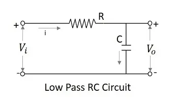
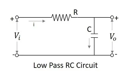
A Filter circuit which allows a set of frequencies that are below a specified value can be termed as a Low pass filter. This filter passes the lower frequencies. The circuit diagram of a low pass filter using RC and RL are as shown below.
The capacitor filter or RC filter and the inductor filter or RL filter both act as low pass filters.
· The RC filter − As the capacitor is placed in shunt, the AC it allows is grounded. This by passes all the high frequency components while allows DC at the output.
· The RL filter − As the inductor is placed in series, the DC is allowed to the output. The inductor blocks AC which is not allowed at the output.
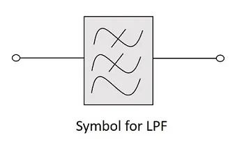
The symbol for a low pass filter (LPF) is as given below.
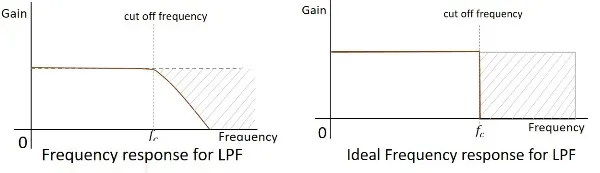
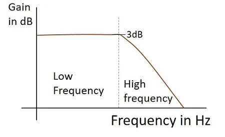
The frequency response of a practical filter is as shown here under and the frequency response of an ideal LPF when the practical considerations of electronic components are not considered will be as follows.
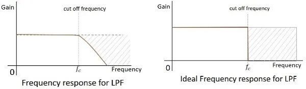
The cut off frequency for any filter is the critical frequency fcfc for which the filter is intended to attenuate (cut) the signal. An ideal filter has a perfect cut-off whereas a practical one has few limitations.
After knowing about the RC and RL filters, one may have an idea that it would be good to add these two circuits in order to have a better response. The following figure shows how the RLC circuit looks like.
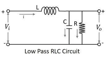
The signal at the input goes through the inductor which blocks AC and allows DC. Now, that output is again passed through the capacitor in shunt, which grounds the remaining AC component if any, present in the signal, allowing DC at the output. Thus we have a pure DC at the output. This is a better low pass circuit than both of them.
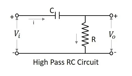
A Filter circuit which allows a set of frequencies that are above a specified value can be termed as a High pass filter. This filter passes the higher frequencies. The circuit diagram of a high pass filter using RC and RL are as shown below.
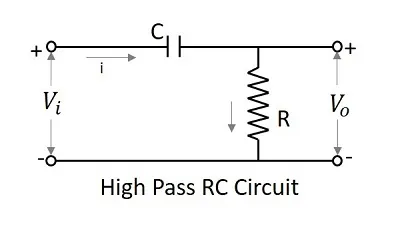
The capacitor filter or RC filter and the inductor filter or RL filter both act as high pass filters.
As the capacitor is placed in series, it blocks the DC components and allows the AC components to the output. Hence the high frequency components appear at the output across the resistor.
As the inductor is placed in shunt, the DC is allowed to be grounded. The remaining AC component, appears at the output. The symbol for a high pass filter (HPF) is as given below.
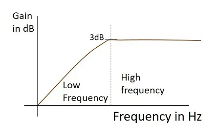
The frequency response of a practical filter is as shown here under and the frequency response of an ideal HPF when the practical considerations of electronic components are not considered will be as follows.
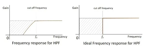
The cut-off frequency for any filter is the critical frequency fcfc for which the filter is intended to attenuate (cut) the signal. An ideal filter has a perfect cut-off whereas a practical one has few limitations.
After knowing about the RC and RL filters, one may have an idea that it would be good to add these two circuits in order to have a better response. The following figure shows how the RLC circuit looks like.
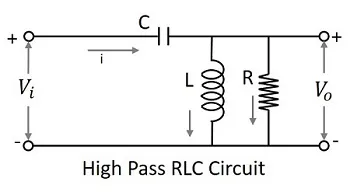
The signal at the input goes through the capacitor which blocks DC and allows AC. Now, that output is again passed through the inductor in shunt, which grounds the remaining DC component if any, present in the signal, allowing AC at the output. Thus we have a pure AC at the output. This is a better high pass circuit than both of them.
A Filter circuit which allows a set of frequencies that are between two specified values can be termed as a Band pass filter. This filter passes a band of frequencies.
As we need to eliminate few of the low and high frequencies, to select a set of specified frequencies, we need to cascade a HPF and a LPF to get a BPF. This can be understood easily even by observing the frequency response curves.
The circuit diagram of a band pass filter is as shown below.
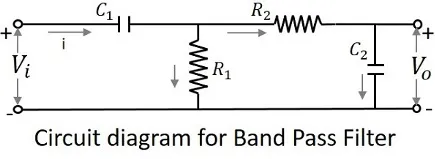
The above circuit can also be constructed using RL circuits or RLC circuits. The above one is a RC circuit chosen for simple understanding.
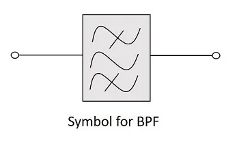
The symbol for a band pass filter (BPF) is as given below.
The frequency response of a practical filter is as shown here under and the frequency response of an ideal BPF when the practical considerations of electronic components are not considered will be as follows.
The cut-off frequency for any filter is the critical frequency fcfc for which the filter is intended to attenuate (cut) the signal. An ideal filter has a perfect cut-off whereas a practical one has few limitations.
A Filter circuit which blocks or attenuates a set of frequencies that are between two specified values can be termed as a Band Stop filter. This filter rejects a band of frequencies and hence can also be called as Band Reject Filter.
As we need to eliminate few of the low and high frequencies, to select a set of specified frequencies, we need to cascade a LPF and a HPF to get a BSF. This can be understood easily even by observing the frequency response curves.
The circuit diagram of a band stop filter is as shown below.
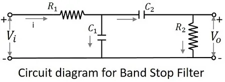
The above circuit can also be constructed using RL circuits or RLC circuits. The above one is a RC circuit chosen for simple understanding.
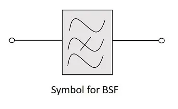
The symbol for a band stop filter (BSF) is as given below.
The frequency response of a practical filter is as shown here under and the frequency response of an ideal BSF when the practical considerations of electronic components are not considered will be as follows.
The cut-off frequency for any filter is the critical frequency fcfc for which the filter is intended to attenuate (cut) the signal. An ideal filter has a perfect cut-off whereas a practical one has few limitations.
Special Functions of LPF and HPF
Low-pass and high-pass filter circuits are used as special circuits in many applications. Low-pass filter (LPF) can work as an Integrator, whereas the high-pass filter (HPF) can work as a Differentiator. These two mathematical functions are possible only with these circuits which reduce the efforts of an electronics engineer in many applications.
At low frequencies, the capacitive reactance tends to become infinite and at high frequencies the reactance becomes zero. Hence at low frequencies, the LPF has finite output and at high frequencies the output is nil, which is same for an integrator circuit. Hence low pass filter can be said to be worked as an integrator.
For the LPF to behave as an integrator
τ≫Tτ≫T
Where τ=RCτ=RC the time constant of the circuit
Then the voltage variation in C is very small.
Vi=iR+1C∫idtVi=iR+1C∫idt
Vi≅iRVi≅iR
Since1C∫idt≪iRSince1C∫idt≪iR
i=ViRi=ViR
SinceV0=1C∫idt=1RC∫Vidt=1τ∫VidtSinceV0=1C∫idt=1RC∫Vidt=1τ∫Vidt
Output∝∫inputOutput∝∫input
Hence a LPF with large time constant produces an output that is proportional to the integral of an input.
The Frequency response of a practical low pass filter, when it works as an Integrator is as shown below.
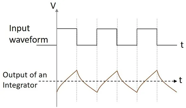
If the integrator circuit is given a sinewave input, the output will be a cosine wave. If the input is a square wave, the output wave form changes its shape and appears as in the figure below.
At low frequencies, the output of a differentiator is zero whereas at high frequencies, its output is of some finite value. This is same as for a differentiator. Hence the high pass filter is said to be behaved as a differentiator.
If time constant of the RC HPF is very much smaller than time period of the input signal, then circuit behaves as a differentiator. Then the voltage drop across R is very small when compared to the drop across C.
Vi=1C∫idt+iRVi=1C∫idt+iR
But iR=V0iR=V0 is small
sinceVi=1C∫idtsinceVi=1C∫idt
i=V0Ri=V0R
SinceVi=1τ∫V0dtSinceVi=1τ∫V0dt
Where τ=RCτ=RC the time constant of the circuit.
Differentiating on both sides,
dVidt=V0τdVidt=V0τ
V0=τdVidtV0=τdVidt
SinceV0∝dVidtSinceV0∝dVidt
The output is proportional to the differential of the input signal.
The Frequency response of a practical high pass filter, when it works as a Differentiator is as shown below.
If the differentiator circuit is given a sinewave input, the output will be a cosine wave. If the input is a square wave, the output wave form changes its shape and appears as in the figure below.
These two circuits are mostly used in various electronic applications. A differentiator circuit produces a constant output voltage when the input applied tends to change steadily. An integrator circuit produces a steadily changing output voltage when the input voltage applied is constant.