The next and the last stage before load, in a power supply system is the Regulator part. Let us now try to understand what a regulator is and what it does.
The part of electronics that deal with the control and conversion of electric power can be termed as Power Electronics. A regulator is an important device when it comes to power electronics as it controls the power output.
For a Power supply to produce a constant output voltage, irrespective of the input voltage variations or the load current variations, there is a need for a voltage regulator.
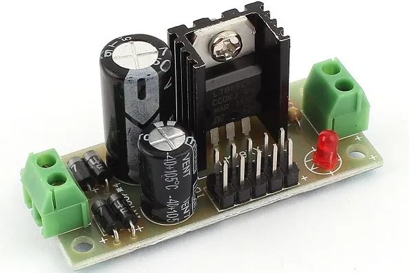
A voltage regulator is such a device that maintains constant output voltage, instead of any kind of fluctuations in the input voltage being applied or any variations in current, drawn by the load. The following image gives an idea of what a practical regulator looks like.
Regulators can be classified into different categories, depending upon their working and type of connection.
Depending upon the type of regulation, the regulators are mainly divided into two types namely, line and load regulators.
· Line Regulator − The regulator which regulates the output voltage to be constant, in spite of input line variations, it is called as Line regulator.
· Load Regulator − The regulator which regulates the output voltage to be constant, in spite of the variations in load at the output, it is called as Load regulator.
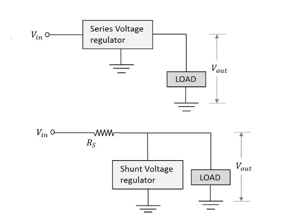
Depending upon the type of connection, there are two type of voltage regulators. They are
The arrangement of them in a circuit will be just as in the following figures.
Let us have a look at other important regulator types.
A Zener voltage regulator is one which uses Zener diode for regulating the output voltage. We have already discussed the details regarding Zener diode in BASIC ELECTRONICS tutorial.
When the Zener diode is operated in the breakdown or Zener region, the voltage across it is substantially constant for a large change of currentthrough it. This characteristic makes Zener diode a good voltage regulator.
The following figure shows an image of a simple Zener regulator.
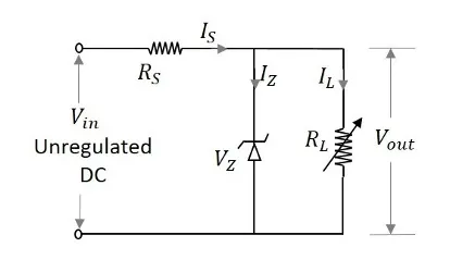
The applied input voltage ViVi when increased beyond the Zener voltage VzVz, then the Zener diode operates in the breakdown region and maintains constant voltage across the load. The series limiting resistor RsRs limits the input current.
The Zener diode maintains the voltage across it constant in spite of load variations and input voltage fluctuations. Hence we can consider 4 cases to understand the working of a Zener voltage regulator.
Case 1 − If the load current ILIL increases, then the current through the Zener diode IZIZ decreases in order to maintain the current through the series resistor RSRS constant. The output voltage Vo depends upon the input voltage Vi and voltage across the series resistor RSRS.
This is can be written as
Vo=Vin−IRsVo=Vin−IRs
Where II is constant. Therefore, VoVo also remains constant.
Case 2 − If the load current ILIL decreases, then the current through the Zener diode IZIZ increases, as the current ISIS through RS series resistor remains constant. Though the current IZIZ through Zener diode increases it maintains a constant output voltage VZVZ, which maintains the load voltage constant.
Case 3 − If the input voltage ViVi increases, then the current ISIS through the series resistor RS increases. This increases the voltage drop across the resistor, i.e. VSVS increases. Though the current through Zener diode IZIZincreases with this, the voltage across Zener diode VZVZ remains constant, keeping the output load voltage constant.
Case 4 − If the input voltage decreases, the current through the series resistor decreases which makes the current through Zener diode IZIZdecreases. But the Zener diode maintains output voltage constant due to its property.
There are a few limitations for a Zener voltage regulator. They are −
Hence a Zener voltage regulator is considered effective for low voltage applications. Now, let us go through the other types of voltage regulators, which are made using transistors.
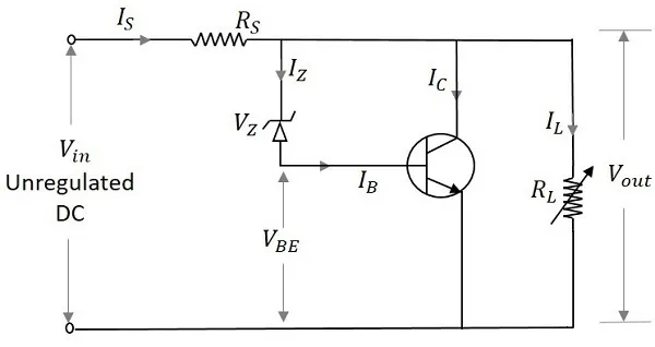
This regulator has a transistor in series to the Zener regulator and both in parallel to the load. The transistor works as a variable resistor regulating its collector emitter voltage in order to maintain the output voltage constant. The figure below shows the transistor series voltage regulator.
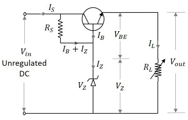
With the input operating conditions, the current through the base of the transistor changes. This effects the voltage across the base emitter junction of the transistor VBEVBE. The output voltage is maintained by the Zener voltage VZVZ which is constant. As both of them are maintained equal, any change in the input supply is indicated by the change in emitter base voltage VBEVBE.
Hence the output voltage Vo can be understood as
VO=VZ+VBEVO=VZ+VBE
The working of a series voltage regulator shall be considered for input and load variations. If the input voltage is increased, the output voltage also increases. But this in turn makes the voltage across the collector base junction VBEVBE to decrease, as the Zener voltage VZVZ remains constant. The conduction decreases as the resistance across emitter collector region increases. This further increases the voltage across collector emitter junction VCE thus reducing the output voltage VOVO. This will be similar when the input voltage decreases.
When the load changes occur, which means if the resistance of the load decreases, increasing the load current ILIL, the output voltage VOVO decreases, increasing the emitter base voltage VBEVBE.
With the increase in the emitter base voltage VBEVBE the conduction increases reducing the emitter collector resistance. This in turn increases the input current which compensates the decrease in the load resistance. This will be similar when the load current increases.
Transistor Series Voltage Regulators have the following limitations −
To minimize these limitations, transistor shunt regulator is used.
A transistor shunt regulator circuit is formed by connecting a resistor in series with the input and a transistor whose base and collector are connected by a Zener diode that regulates, both in parallel with the load. The figure below shows the circuit diagram of a transistor shunt regulator.
If the input voltage increases, the VBEVBE and VOVO also gets increased. But this happens initially. Actually when VinVin increases, the current IinIin also increases. This current when flows through RS, causes a voltage drop VSVSacross the series resistor, which also gets increased with VinVin. But this makes VoVo to decrease. Now this decrease in VoVo compensates the initial increase maintaining it to be constant. Hence VoVo is maintained constant. If the output voltage decreases instead, the reverse happens.
If the load resistance decreases, there should be decrease in the output voltage VoVo. The current through the load increases. This makes the base current and collector current of the transistor to decrease. The voltage across the series resistor becomes low, as the current flows heavily. The input current will be constant.
The output voltage appears will be the difference between the applied voltage ViVi and the series voltage drop VsVs. Hence the output voltage will be increased to compensate the initial decrease and hence maintained constant. The reverse happens if the load resistance increases.
Voltage Regulators are now-a-days available in the form of Integrated Circuits (ICs). These are in short called as IC Regulators.
Along with the functionality like a normal regulator, an IC regulator has the properties like thermal compensation, short circuit protection and surge protection which are built into the device.
IC regulators can be of the following types −
Let us now discuss them in detail.
The output of these regulators is fixed to a specific value and the values are positive, which means the output voltage provided is positive voltage.
The most used series is 7800 series and the ICs will be like IC 7806, IC 7812 and IC 7815 etc. which provide +6v, +12v and +15v respectively as output voltages. The figure below shows the IC 7810 connected to provide a fixed 10v positive regulated output voltage.
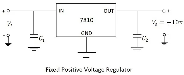
In the above figure, the input capacitor C1C1 is used to prevent unwanted oscillations and the output capacitor C2C2 acts as a line filter to improve transient response.
The output of these regulators is fixed to a specific value and the values are negative, which means the output voltage provided is negative voltage.
The most used series is 7900 series and the ICs will be like IC 7906, IC 7912 and IC 7915 etc. which provide -6v, -12v and -15v respectively as output voltages. The figure below shows the IC 7910 connected to provide a fixed 10v negative regulated output voltage.
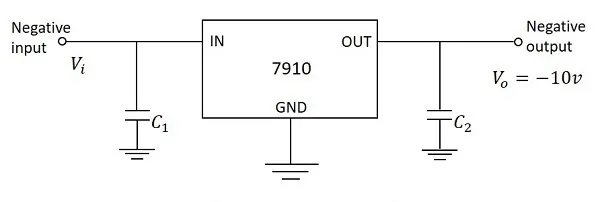
In the above figure, the input capacitor C1C1 is used to prevent unwanted oscillations and the output capacitor C2C2 acts as a line filter to improve transient response.
An adjustable voltage regulator has three terminals IN, OUT and ADJ. The input and output terminals are common whereas the adjustable terminal is provided with a variable resistor which lets the output to vary between a wide range.
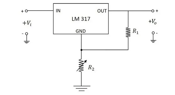
The above figure shows an unregulated power supply driving a LM 317 adjustable IC regulator which is commonly used. The LM 317 is a three terminal positive adjustable voltage regulator and can supply 1.5A of load current over an adjustable output range of 1.25v to 37v.
A dual-tracking regulator is used when split-supply voltages are needed. These provide equal positive and negative output voltages. For example, the RC4195 IC provides D.C. outputs of +15v and -15v. This needs two unregulated input voltages such as the positive input may vary from +18v to +30v and negative input may vary from -18v to -30v.
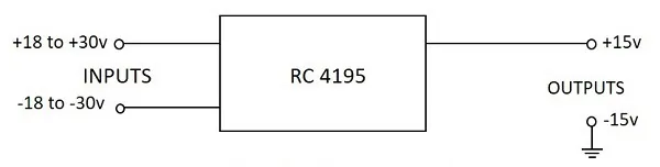
The above image shows a dual-tracking RC4195 IC regulator. The adjustable dual-tacking regulators are also available whose outputs vary between two rated limits.