Whenever there arises the need to convert an AC to DC power, a rectifier circuit comes for the rescue. A simple PN junction diode acts as a rectifier. The forward biasing and reverse biasing conditions of the diode makes the rectification.
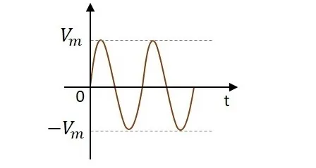
An alternating current has the property to change its state continuously. This is understood by observing the sine wave by which an alternating current is indicated. It raises in its positive direction goes to a peak positive value, reduces from there to normal and again goes to negative portion and reaches the negative peak and again gets back to normal and goes on.
During its journey in the formation of wave, we can observe that the wave goes in positive and negative directions. Actually it alters completely and hence the name alternating current.
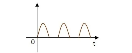
But during the process of rectification, this alternating current is changed into direct current DC. The wave which flows in both positive and negative direction till then, will get its direction restricted only to positive direction, when converted to DC. Hence the current is allowed to flow only in positive direction and resisted in negative direction, just as in the figure below.
The circuit which does rectification is called as a Rectifier circuit. A diode is used as a rectifier, to construct a rectifier circuit.
There are two main types of rectifier circuits, depending upon their output. They are
A Half-wave rectifier circuit rectifies only positive half cycles of the input supply whereas a Full-wave rectifier circuit rectifies both positive and negative half cycles of the input supply.
The name half-wave rectifier itself states that the rectification is done only for half of the cycle. The AC signal is given through an input transformer which steps up or down according to the usage. Mostly a step down transformer is used in rectifier circuits, so as to reduce the input voltage.
The input signal given to the transformer is passed through a PN junction diode which acts as a rectifier. This diode converts the AC voltage into pulsating dc for only the positive half cycles of the input. A load resistor is connected at the end of the circuit. The figure below shows the circuit of a half wave rectifier.
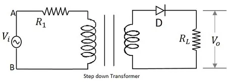
TThe input signal is given to the transformer which reduces the voltage levels. The output from the transformer is given to the diode which acts as a rectifier. This diode gets ON (conducts) for positive half cycles of input signal. Hence a current flows in the circuit and there will be a voltage drop across the load resistor. The diode gets OFF (doesn’t conduct) for negative half cycles and hence the output for negative half cycles will be, iD=0iD=0 and Vo=0Vo=0.
Hence the output is present for positive half cycles of the input voltage only (neglecting the reverse leakage current). This output will be pulsating which is taken across the load resistor.
The input and output waveforms are as shown in the following figure.
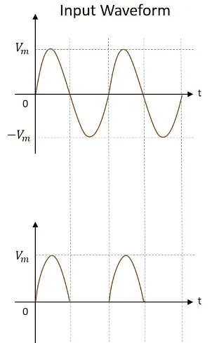
Hence the output of a half wave rectifier is a pulsating dc. Let us try to analyze the above circuit by understanding few values which are obtained from the output of half wave rectifier.
To analyze a half-wave rectifier circuit, let us consider the equation of input voltage.
vi=Vmsinωtvi=Vmsinωt
VmVm is the maximum value of supply voltage.
Let us assume that the diode is ideal.
The current i in the diode or the load resistor RLRL is given by
i=Imsinωtfor0≤ωt≤2πi=Imsinωtfor0≤ωt≤2π
i=0forπ≤ωt≤2πi=0forπ≤ωt≤2π
Where
Im=VmRf+RLIm=VmRf+RL
The average current IdcIdc is given by
Idc=12π∫2π0id(ωt)Idc=12π∫02πid(ωt)
=12π[∫π0Imsinωtd(ωt)+∫2π00d(ωt)]=12π[∫0πImsinωtd(ωt)+∫02π0d(ωt)]
=12π[Im{−cosωt}π0]=12π[Im{−cosωt}0π]
=12π[Im{+1−(−1)}]=Imπ=0.318Im=12π[Im{+1−(−1)}]=Imπ=0.318Im
Substituting the value of ImIm, we get
Idc=Vmπ(Rf+RL)Idc=Vmπ(Rf+RL)
If RL>>RfRL>>Rf, then
Idc=VmπRL=0.318VmRLIdc=VmπRL=0.318VmRL
The DC output voltage is given by
Vdc=Idc×RL=Imπ×RLVdc=Idc×RL=Imπ×RL
=Vm×RLπ(Rf+RL)=Vmπ{1+(Rf/RL)}=Vm×RLπ(Rf+RL)=Vmπ{1+(Rf/RL)}
If RL>>RfRL>>Rf, then
Vdc=Vmπ=0.318VmVdc=Vmπ=0.318Vm
The value of RMS current is given by
Irms=[12π∫2π0i2d(ωt)]12Irms=[12π∫02πi2d(ωt)]12
Irms=[12π∫2π0I2msin2ωtd(ωt)+12π∫2ππ0d(ωt)]12Irms=[12π∫02πIm2sin2ωtd(ωt)+12π∫π2π0d(ωt)]12
=[I2m2π∫π0(1−cos2ωt2)d(ωt)]12=[Im22π∫0π(1−cos2ωt2)d(ωt)]12
=[I2m4π{(ωt)−sin2ωt2}π0]12=[Im24π{(ωt)−sin2ωt2}0π]12
=[I2m4π{π−0−sin2π2+sin0}]12=[Im24π{π−0−sin2π2+sin0}]12
=[I2m4π]12=Im2=[Im24π]12=Im2
=Vm2(Rf+RL)=Vm2(Rf+RL)
RMS voltage across the load is
Vrms=Irms×RL=Vm×RL2(Rf+RL)Vrms=Irms×RL=Vm×RL2(Rf+RL)
=Vm2{1+(Rf/RL)}=Vm2{1+(Rf/RL)}
If RL>>RfRL>>Rf, then
Vrms=Vm2Vrms=Vm2
Any circuit needs to be efficient in its working for a better output. To calculate the efficiency of a half wave rectifier, the ratio of the output power to the input power has to be considered.
The rectifier efficiency is defined as
η=d.c.powerdeliveredtotheloada.c.inputpowerfromtransformersecondary=PacPdcη=d.c.powerdeliveredtotheloada.c.inputpowerfromtransformersecondary=PacPdc
Now
Pdc=(Idc)2×RL=ImRLπ2Pdc=(Idc)2×RL=ImRLπ2
Further
Pac=Pa+PrPac=Pa+Pr
Where
Pa=powerdissipatedatthejunctionofdiodePa=powerdissipatedatthejunctionofdiode
=I2rms×Rf=I2m4×Rf=Irms2×Rf=Im24×Rf
And
Pr=powerdissipatedintheloadresistancePr=powerdissipatedintheloadresistance
=I2rms×RL=I2m4×RL=Irms2×RL=Im24×RL
Pac=I2m4×Rf+I2m4×RL=I2m4(Rf+RL)Pac=Im24×Rf+Im24×RL=Im24(Rf+RL)
From both the expressions of PacPac and PdcPdc, we can write
η=I2mRL/π2I2m(Rf+RL)/4=4π2RL(Rf+RL)η=Im2RL/π2Im2(Rf+RL)/4=4π2RL(Rf+RL)
=4π21{1+(Rf/RL)}=0.406{1+(Rf/RL)}=4π21{1+(Rf/RL)}=0.406{1+(Rf/RL)}
Percentage rectifier efficiency
η=40.6{1+⟮Rf/RL⟯}η=40.6{1+⟮Rf/RL⟯}
Theoretically, the maximum value of rectifier efficiency of a half wave rectifier is 40.6% when Rf/RL=0Rf/RL=0
Further, the efficiency may be calculated in the following way
η=PdcPac=(Idc)2RL(Irms)2RL=(Vdc/RL)2RL(Vrms/RL)2RL=(Vdc)2(Vrms)2η=PdcPac=(Idc)2RL(Irms)2RL=(Vdc/RL)2RL(Vrms/RL)2RL=(Vdc)2(Vrms)2
=(Vm/π)2(Vm/2)2=4π2=0.406=(Vm/π)2(Vm/2)2=4π2=0.406
=40.6%=40.6%
The rectified output contains some amount of AC component present in it, in the form of ripples. This is understood by observing the output waveform of the half wave rectifier. To get a pure dc, we need to have an idea on this component.
The ripple factor gives the waviness of the rectified output. It is denoted by y. This can be defined as the ratio of the effective value of ac component of voltage or current to the direct value or average value.
γ=ripplevoltaged.cvoltage=rmsvalueofa.c.componentd.c.valueofwave=(Vr)rmsvdcγ=ripplevoltaged.cvoltage=rmsvalueofa.c.componentd.c.valueofwave=(Vr)rmsvdc
Here,
(Vr)rms=V2rms−V2dc−−−−−−−−√(Vr)rms=Vrms2−Vdc2
Therefore,
γ=V2rms−V2dc−−−−−−−−√Vdc=(VrmsVdc)2−1−−−−−−−−−−−√γ=Vrms2−Vdc2Vdc=(VrmsVdc)2−1
Now,
Vrms=[12π∫2π0V2msin2ωtd(ωt)]12Vrms=[12π∫02πVm2sin2ωtd(ωt)]12
=Vm[14π∫π0(1−cos2ωt)d(ωt)]12=Vm2=Vm[14π∫0π(1−cos2ωt)d(ωt)]12=Vm2
Vdc=Vav=12π[∫π0Vmsinωtd(ωt)+∫2π00.d(ωt)]Vdc=Vav=12π[∫0πVmsinωtd(ωt)+∫02π0.d(ωt)]
=Vm2π[−cosωt]π0=Vmπ=Vm2π[−cosωt]0π=Vmπ
γ=[{(Vm/2)(Vm/π)}2−1]−−−−−−−−−−−−−−−⎷={(π2)2−1}−−−−−−−−−−−√=1.21γ=[{(Vm/2)(Vm/π)}2−1]={(π2)2−1}=1.21
The ripple factor is also defined as
γ=(Ir)rmsIdcγ=(Ir)rmsIdc
As the value of ripple factor present in a half wave rectifier is 1.21, it means that the amount of a.c. present in the output is 121%121% of the d.c. voltage
The current through the load may vary depending upon the load resistance. But even at such condition, we expect our output voltage which is taken across that load resistor, to be constant. So, our voltage needs to be regulated even under different load conditions.
The variation of D.C. output voltage with change in D.C. load current is defined as the Regulation. The percentage regulation is calculated as follows.
Percentageregulation=Vnoload−VfullloadVfullload×100%Percentageregulation=Vnoload−VfullloadVfullload×100%
The lower the percentage regulation, the better would be the power supply. An ideal power supply will have a zero percentage regulation.
The D.C. power to be delivered to the load, in a rectifier circuit decides the rating of the transformer used in a circuit.
So, the transformer utilization factor is defined as
TUF=d.c.powertobedeliveredtotheloada.c.ratingofthetransformersecondaryTUF=d.c.powertobedeliveredtotheloada.c.ratingofthetransformersecondary
=Pd.cPa.c(rated)=Pd.cPa.c(rated)
According to the theory of transformer, the rated voltage of the secondary will be
Vm/2–√Vm/2
The actual R.M.S. voltage flowing through it will be
Im/2Im/2
Therefore
TUF=(Im/π)2×RL(Vm/2–√)×(Im/2)TUF=(Im/π)2×RL(Vm/2)×(Im/2)
But
Vm=Im(Rf+RL)Vm=Im(Rf+RL)
Therefore
TUF=(Im/π)2×RL{Im(Rf+RL)/2–√}×(Im/2)TUF=(Im/π)2×RL{Im(Rf+RL)/2}×(Im/2)
=22–√π2×RL(Rf+RL)=22π2×RL(Rf+RL)
=22–√π2=0.287=22π2=0.287
A diode when connected in reverse bias, should be operated under a controlled level of voltage. If that safe voltage is exceeded, the diode gets damaged. Hence it is very important to know about that maximum voltage.
The maximum inverse voltage that the diode can withstand without being destroyed is called as Peak Inverse Voltage. In short, PIV.
Here the PIV is nothing but Vm
This can be understood as the mathematical mean of absolute values of all points on the waveform. The form factor is defined as the ratio of R.M.S. value to the average value. It is denoted by F.
F=rmsvalueaveragevalue=Im/2Im/π=0.5Im0.318Im=1.57F=rmsvalueaveragevalue=Im/2Im/π=0.5Im0.318Im=1.57
The value of peak in the ripple has to be considered to know how effective the rectification is. The value of peak factor is also an important consideration. Peak factor is defined as the ratio of peak value to the R.M.S. value.
Therefore
PeakFactor=Peakvaluer.m.svalue=VmVm/2=2PeakFactor=Peakvaluer.m.svalue=VmVm/2=2
All these are the important parameters to be considered while studying about a rectifier.