Protections in Electric Power Systems
D IFFERENT TYPES of protections are installed to protect the equipment in an electric power system. Their task is to disconnect failed or overloaded equipment or parts of the system to avoid unnecessary damages on equipment and personnel. The purpose is also to limit the impact of failures on the parts of the system that have not failed. Special types of protection are the “system protections”. Their task is to prevent collapse (black out) of the system or parts of the system. An intensive development of protections based on modern information technology is going on both regarding hardware and software. On the hardware side microprocessors have been used over a long time to implement different functions in the protections, and with the recent developments more and more complicated functions can be implemented in a reliable way. Powerful methods like signal processing, state estimation, and “artificial intelligence”, are being integrated into the protections. In general the functions which earlier were handled with separate relays are increasingly being integrated with other functional units for control and supervision. Furthermore, more complicated criteria for activation of protections can be applied. The interested reader is referred to the literature for further information. The summary here is concentrated on general principles for protections.
Design of Protections
A protection for an electric power system comprises the following parts:
• Measurement device with current- and/or voltage transformers and other sensors measuring the relevant quantities.
• Relay which when certain conditions are fulfilled sends signals to a circuit breaker or another switching device. This relay was earlier aseparate unit, but can in modern protections be a part of a larger unit for protection, supervision and control.
• Circuit breakers which execute the given instruction(s) from the relay.
• Telecommunication system is mainly used at distance (line) protections to get a faster and more reliable performance.
• Power supply systems which shall secure the power supply to the protection system, even with faults in the system. The requirements on a protection system are that they should be dependable, secure, selective, sensitive, and fast.
• Dependability means that the protection should react and do its action when a fault occurs for which it is designed to react for. To achieve desired dependability double or even triple sets of certain parts of the protection or of signal paths might be needed. Malfunctions can be divided into ”not occurring” operations (which are actions that were supposed to happen but did not) and ”unwanted” operations (which are actions that happened although they should not have). Normally not occurring operations are more serious malfunctions than unwanted ones.
• Security means that the protection should not react when no fault occurs or when a fault for which it is not intended to react occurs.
• Sensitivity is needed to detect failures which cause small fault currents, e.g. high impedance faults. This implies that the risk for misoperations increases at “small” disturbances, e.g. at energisation of transformers, or at high load operation but normal operation.
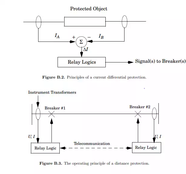
• The protection should react fast to secure that damages on persons and equipment are prevented or limited. The protections are often classified according to the object that they protect. An example is shown in Figure B.1. If a failure occurs within an indicated area in Figure B.1 this area should be isolated from the rest of the network. Many of the protections which protect separate pieces of equipment or parts of a system which occupy a limited physical area are so called current differential protections. These protections measure the difference between two currents, which in normal operation should be equal, and the protection is activated if this deviation exceeds a predetermined value. Both differences in amplitude and phase can trigger the relay.
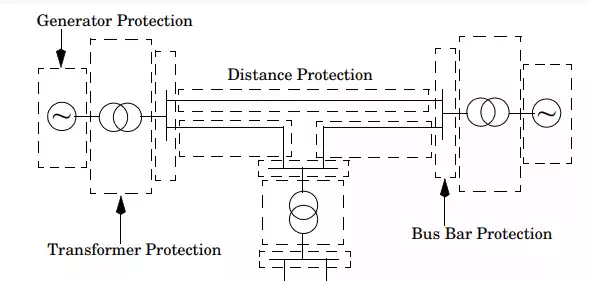
The different protection zones in a power systems.
Distance Protections
General Principles
So called distance protections are important protections concerning stability and dynamics in a power system. Their task is to disconnect faulted lines or cables. Since large parts of the power system consist physically of lines and these are exposed to different disturbances, e.g. lightning strokes, down falling trees etc., it is important that those faults can be isolated to minimise the impact on the rest of the system. The most common faults are ground (earth) faults, i.e. short circuits between two or more phases and ground (shunt faults). Also interruptions in the lines can occur (series faults). The operating principle of the distance protection is shown in Figure B.3. Current and voltage are measured in both ends of the line and from these an apparent impedance can be calculated: Z = U/I. In normal operation this impedance varies within a certain area (large and almost resistive values on Z), but if a fault occurs, it will drastically change. The given value depends on where on the line the failure occurs, and from system parameters as line data and short circuit capacity, it can be calculated where the fault has occurred. For each distance protection there are several protection zones defined in the Z plane according to Figure B.4. A low value on Z implies that the fault is close to the measurement. From line data and short circuit capacity
it can then be decided if the fault is in the protected line, within Zone 1, or not. If that is the case, a trip order is given to the breaker at the same station within some milliseconds, typically 10 ms, after Z has reached Zone 1. At the same time a trip order is given to the breaker in the other end of the line. This latter trip order is not needed for isolation of the fault, if the protection system in the other end works as it should, but this trip order (transfer trip) increases the security in the system. If the measured value on Z is in Zone 2 or 3, it implies that the fault is outside the actual line. This implies that neither breaker 1 nor 2 in Figure B.3 shall be opened. If the breakers, which according to the protection plane should isolate the fault, are not operated by some reason, other breakers which are further away from the fault must isolate it. These secondary
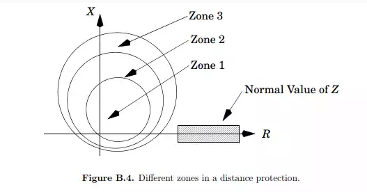
breakers will be used first after it is clear that the primary breakers have not isolated the fault. Therefore if, Z is in Zone 2, the breaker does not get the trip order until typically some hundred milliseconds have passed. To coordinate and tune the settings of the protections to give a fast, reliable, sensitive and selective protection system is a complicated and an important task in an electric power system. In modern protection systems different areas can be defined according to Figure B.4 with in principal arbitrary geometric shapes, which facilitates the work. A plan comprising the different areas of protections and time settings is usually called a selectivity plan. The work to establish a selectivity plan is often very time consuming because it should be appropriate for every feasible state of operation, i.e. for different numbers of generators and lines connected and also at different load levels. Often trade-offs must be made to reach acceptable results.