Machine Models
S YNCHRONOUS MACHINES, i.e. practically all generators together with synchronous motors and synchronous compensators, are the most important power system components in the analysis of electro-mechanical oscillations in power systems. The oscillations are manifested in that the rotors of the synchronous machines do not rotate with constant angular velocity corresponding to system frequency, but superimposed are low frequency oscillations, typically 0.1 – 4 Hz. It is important that these superimposed oscillations are not too large, because then the stability of the power system can be endangered. A correct description of these oscillations often requires detailed models of many different system components, but to get an understanding of and insight into the basic physical phenomena and processes that determine the stability it is often sufficient to employ the simple model that will be derived and motivated in this chapter. This simplified model of the synchronous machine together with a simple model of the power transmission system provide a description that will be used in chapter 11. As the name electro-mechanical oscillations suggests, both electrical and mechanical phenomena are involved, i.e. both currents in and voltages across different windings in the machines but also the mechanical motion of the rotor. Therefore, models of both electrical and mechanical parts of the synchronous machine are needed.
Design and Operating Principle:
In the synchronous machine a magnetized rotor creates a rotating magnetic field in the air gap. If the rotor field is ideally sinusoidal and if the rotor rotates at constant speed, this will induce ideally sinusoidal voltages in the stator windings.
Cross-sections through different rotor types
If the machine terminals are connected, the currents flowing in the stator windings create a second rotating magnetic field which causes a torque on the rotor. In a synchronous motor, this torque drives a mechanical load; in a synchronous generator, the magnetic torque opposes the mechanical driving torque of the prime mover (e.g. a turbine). Under balanced, steady-state conditions the magnetic torque is equal to the mechanical torque, and so the rotor continues to rotate at constant speed.
Rotor Types
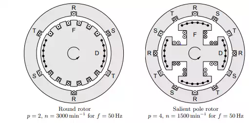
The magnetic rotor field is generated by a field winding F on the rotor which is fed with an adjustable direct current. In addition, the rotor has a shortcircuited damper winding D at the surface. This winding serves to dampen electrical and mechanical oscillations and to shield the field winding from inverse rotating fields in case of asymmetries or harmonics in the stator currents. (In rotors without an explicitly realized damper winding, eddy currents in the rotor iron can have a similar effect.) Depending on the application of the generator, two different types of rotors are used that are shown in Figure 9.1.
Round Rotor
Round rotors are used with high-speed turbines such as steam or gas turbines. For this reason, generators with round rotors are also called turbo generators. They can have ratings as high as 1800 MVA per unit. Due to the large centrifugal forces, the rotor consists of a long, narrow, solid steel cylinder. The field windings are mounted in slots that are mill-cut into about 2/3 of the perimeter. Because of the discrete distribution of the windings on the

Simplified arrangement of a stator with a solid, unwound rotor.
rotor surface, the magnetic flux density in the air gap always has a stair-step form. Through proper distribution of the windings these stair-steps can be made approximately sinusoidal!
Salient Pole
Rotor Salient pole rotors are used with low-speed hydro turbines with rated powers of up to 800 MVA per unit. In order to obtain the appropriate electrical power frequency in spite of the low rotor speed, salient pole rotors typically have multiple pole pairs. For run-of-river power stations the number of poles can be as high as p = 200! Such rotors have very large diameters (several meters) and short lengths. The field windings are mounted on the individual poles. By properly designing the geometric form of the poles, the magnetic flux density in the air gap at the stator surface can also be made approximately sinusoidal!
Stator Field
The magnetic stator field is generated by an alternating three-phase current flowing in the stator windings. The variation of this field in space and time can best be studied using the simplified arrangement shown in Figure 9.2. In this arrangement, the stator has only one pole pair and the slots are assumed to be infinitely narrow. The rotor is replaced by a solid, unwound cylinder. The stator field is derived here for a stator with one single pole pair. The transfer to the case of a stator with p poles is left as an exercise to the reader. The magnetic field strength in the iron is neglected and the induction in the air gap is assumed to be radial. Due to the π-symmetry of the set-up
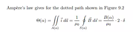
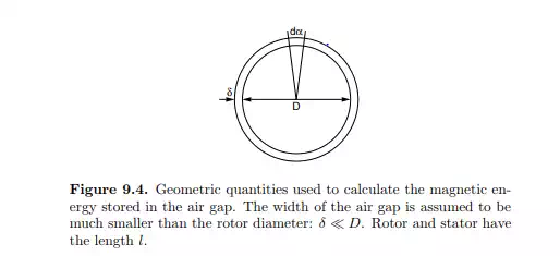
where A(α) is the area enclosed by the path, δ is the width of the air gap, B(α) is the flux density in the air gap at the angle α, and Θ(α) is the total flux linkage (or number of ampere windings) enclosed by the path.
One single-phase winding
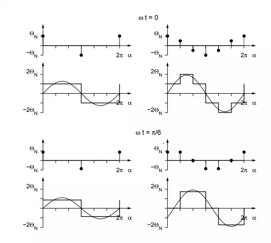
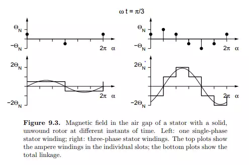
If only phase R is fed by an alternating current, the total enclosed flux linkage is either +w · iR(t) or −w · iR(t), depending on whether the path encloses the upper slot (0 < α < π) or the lower one (π < α < 2π). w is the number of windings in one slot. The left side of Figure 9.3 shows the flux linkage of a single-phase winding plotted against the angle α for different instants of time. Since B(α) is directly proportional to Θ(α) as shown in eq. (9.1), the magnetic field in the air gap is a rectangular, standing wave with a variable amplitude.
Three-phase windings
If the three phases R, S and T are fed by an alternating three-phase current, the integration path in Figure 9.2 always encloses three slots that carry windings with different momentary currents. The resulting total flux as a function of the angle α is thus a superposition of three rectangular curves that are shifted by 2/3 · π and have different amplitudes. This is shown on the right side of Figure 9.3. It is evident that the fundamental component of the total flux is a traveling wave with a constant amplitude which moves with the angular velocity ω. This angular velocity of the stator field is the same as the angular frequency of the alternating currents. In a real stator, the windings are of course not concentrated in infinitely narrow slots. Instead, they are distributed among several slots of finite extent – possibly with a different number of windings in different slots. Through proper design the magnetic field in the air gap can be made approximately sinusoidal.
It should be noted that this simplified treatment of the stator field is only applicable for generators with round rotors where the air gap has a constant width. In the case of a salient pole rotor, the width of the air gap is variable, and therefore the magnetic stator field depends not only on the momentary winding currents but also on the momentary rotational angle of the rotor. In some cases, the differences between round rotor and salient pole rotor can be neglected (as will be done frequently in the remainder of this chapter). However, it should be kept in mind that this is a simplification which needs to be justified from case to case.
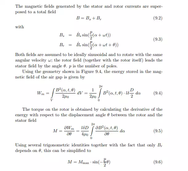
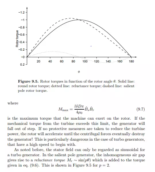
Magnetic Torque