Wye (Y) - Delta (∆) OR Delta (∆)-Wye (Y) Transformations
Introduction
There are certain circuit configurations that cannot be simplified by series-parallel combination alone. A simple transformation based on mathematical technique is readily simplifies the electrical circuit configuration. A circuit configuration shown below
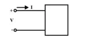
(A) One port network
is a general one-port circuit. When any voltage source is connected across the terminals, the current entering through any one of the two terminals, equals the current leaving the other terminal. For example, resistance, inductance and capacitance acts as a one-port. On the other hand, a two-port is a circuit having two pairs of terminals. Each pair behaves as a one-port; current entering in one terminal must be equal to the current living the other terminal.
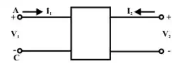
(B) Two port network
Fig.(b) can be described as a four-terminal network, for convenience subscript 1 to refer to the variables at the input port (at the left) and the subscript 2 to refer to the variables at the output port (at the right). The most important subclass of two-port networks is the one in which the minus reference terminals of the input and output ports are at the same. This circuit configuration is radially possible to consider the ‘π or Δ ’ – network also as a three-terminal network in fig.(c). Another frequently encountered circuit configuration that shown in fig.(d) is approximately referred to as a three terminal Y connected circuit as well as two-port circuit.
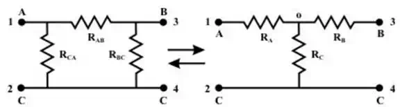
(C) (D)
The name derives from the shape or configuration of the circuit diagrams, which look respectively like the letter Y and the Greek capital letter Δ.
Delta (Δ) – Wye (Y) conversion
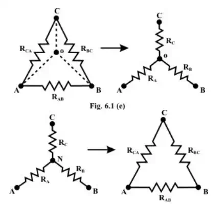
(F)
These configurations may often be handled by the use of a Δ −Y or Y −Δ transformation. One of the most basic three-terminal network equivalent is that of three resistors connected in “Delta ” and in “Wye ( ”. These two circuits identified in fig and Fig.(f) are sometimes part of a larger circuit and obtained their names from their configurations. These three terminal networks can be redrawn as four-terminal networks as shown in fig(c) and fig.(d). We can obtain useful expression for direct transformation or conversion from Δ to Y or Y to Δ by considering that for equivalence the two networks have the same resistance when looked at the similar pairs of terminals.