Single line representation of power system
Trying to represent a practical power system where a lot of interconnections between several generating stations involving a large number of transformers using three lines corresponding to R, Y and B phase will become unnecessary clumsy and complicated. To avoid this, a single line along with some symbolical representations for generator, transformers substation buses are used to represent a power system rather neatly.
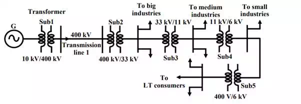
Single line representation of power system.
As another example, an interconnected power system is represented in the self-explained figure– it is hoped that you understand the important features communicated about the system through this figure.
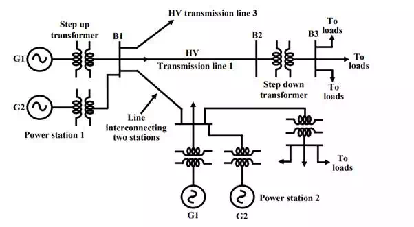
Single line representation of power system.
Distribution system
Till now we have learnt how power at somewhat high voltage (say 33 kV) is received in a substation situated near load centre (a big city). The loads of a big city are primarily residential complexes, offices, schools, hotels, street lighting etc. These types of consumers are called LT (low tension) consumers. Apart from this there may be medium and small-scale industries located in the outskirts of the city. LT consumers are to be supplied with single phase, 220 V, 40 Hz. We shall discuss here how this is achieved in the substation receiving power at 33 kV. The scheme is shown in figure.
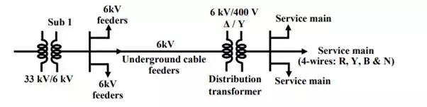
Typical Power distribution scheme.
Power receive at a 33-kV substation is first stepped down to 6 kV and with the help of underground cables (called feeder lines), power flow is directed to different directions of the city. At the last level, step down transformers are used to step down the voltage form 6 kV to 400 V. These transformers are called distribution transformers with 400 V, star connected secondary. You must have noticed such transformers mounted on poles in cities beside the roads. These are called pole mounted substations. From the secondary of these transformers 4 terminals (R, Y, B and N) come out. N is called the neutral and taken out from the common point of star connected secondary. Voltage between any two phases (i.e., R-Y, Y-B and B-R) is 400 V and between any phase and neutral is 230 V(= 400 3). Residential buildings are supplied with single phase 230V, 50Hz. So individual are to be supplied with any one of the phases and neutral. Supply authority tries to see that the loads remain evenly balanced among the phases as far as possible. Which means roughly one third of the consumers will be supplied from R-N, next one third from Y-N and the remaining one third from B-N. The distribution of power from the pole mounted substation can be done either by (1) overhead lines (bare conductors) or by (2) underground cables. Use of overhead lines although cheap, is often accident prone and also theft of power by hooking from the lines take place. Although costly, in big cities and thickly populated areas underground cables for distribution of power, are used.