Parallel circuit
The circuit, with resistance R, inductance L, and a capacitor, C in parallel (Fig a) is connected to a single-phase variable frequency ( f ) supply.
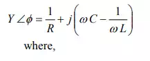
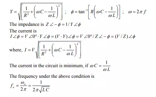
The total admittance of the circuit is
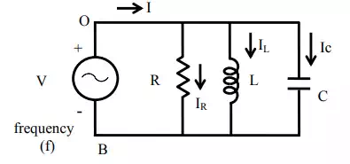
(a) Circuit diagram
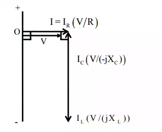
(b) Phasor Diagram
This condition under which the magnitude of the total (supply) current is minimum, or the magnitude of the admittance is minimum (which means that the impedance is maximum), is called resonance. It may be noted that, for parallel circuit, the current or admittance is minimum (the impedance being maximum), while for series circuit, the current is maximum (the impedance being minimum). The frequency under this condition with the constant values of inductance L, and capacitance C, is called resonant frequency. If the capacitance is variable, and the frequency, f is kept constant, the value of the capacitance needed to produce this condition is


In the two cases of series and parallel circuits described earlier, all components, including the inductance, are assumed to be ideal, which means that the inductance is lossless, having no resistance. But, in actual case, especially with an iron-cored choke coil, normally a resistance r is assumed to be in series with the inductance L, to take care of the winding resistance and also the iron loss in the core. In an air-cored coil, the winding resistance may be small, and no loss occurs in the air core.
An iron-cored choke coil is connected in parallel to capacitance, and the combination is fed to an ac supply.

(a) Circuit diagram.
The total admittance of the circuit is
![]()
If the magnitude of the admittance is to be minimum, then
The frequency is
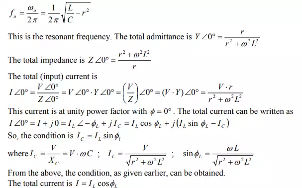
The value, as given here, can be easily obtained. The phasor diagram is shown in Fig b. It may also be noted that the magnitude of the total current is minimum, while the magnitude of the impedance is maximum.
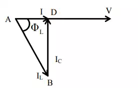
(b) Phasor Diagram
Example
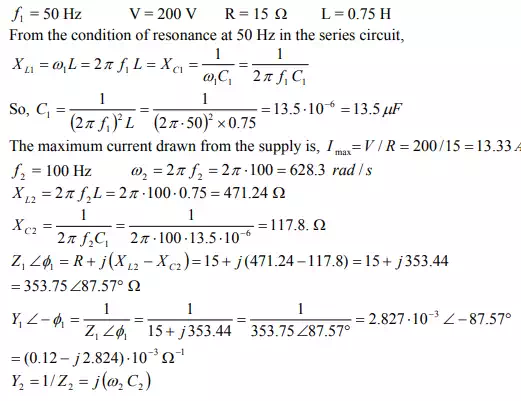
A coil, having a resistance of 15 Ω and an inductance of 0.75 H, is connected in series with a capacitor (Fig a. The circuit draws maximum current, when a voltage of 200 V at 50 Hz is applied. A second capacitor is then connected in parallel to the circuit (Fig b). What should be its value, such that the combination acts like a noninductive resistance, with the same voltage (200 V) at 100 Hz? Calculate also the current drawn by the two circuits.
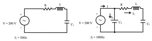
(a) Circuit diagram (b) Circuit diagram
Solution
As the combination is resistive in nature, the total admittance is
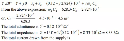
![]()
The phasor diagram for the circuit (Fig b) is shown in Fig c.
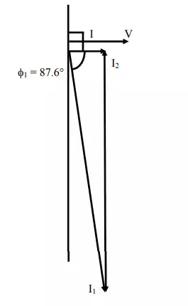
(c) Phasor diagram
The condition for resonance in both series and parallel circuits fed from single phase ac supply is described. It is shown that the current drawn from the supply is at unity power factor (upf) in both cases. The value of the capacitor needed for resonant condition with a constant frequency supply, and the resonant frequency with constant value of capacitance, have been derived. Also taken up is the case of a lossy inductance coil in parallel with a capacitor under variable frequency supply, where the total current will be at upf. The quality factor of the coil and the bandwidth of the series circuit with known value of capacitance have been determined. This is the final lesson in this module of single phase ac circuits. In the next module, the circuits fed from three phase ac supply will be described.