Resonance in Series Circuits
Series circuit
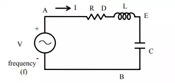
(a) Circuit diagram
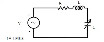
The circuit, with resistance R, inductance L, and a capacitor, C in series (Fig a) is connected to a single-phase variable frequency ( f ) supply.
The total impedance of the circuit is
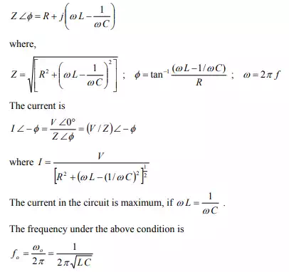
This condition under the magnitude of the current is maximum, or the magnitude of the impedance is minimum, is called resonance. The frequency under this condition with the constant values of inductance L, and capacitance C, is called resonant frequency. If the capacitance is variable, and the frequency, is kept constant, the value of the capacitance needed to produce this condition is
![]()
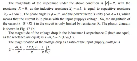
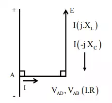
(b) Phasor Diagram
frequency supply is shown in Fig.
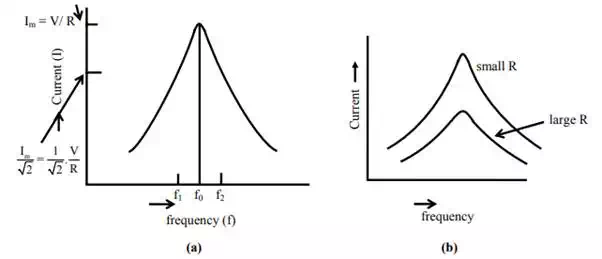
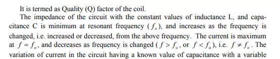
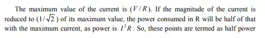
Variation of current under variable frequency supply
It can be observed that, to improve the quality factor (Q) of a coil, it must be designed to have its resistance, R as low as possible. This also results in reduction of band width and losses (for same value of current). But if the resistance, R cannot be decreased, then Q will decrease, and also both band width and losses will increase.
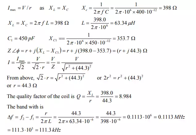
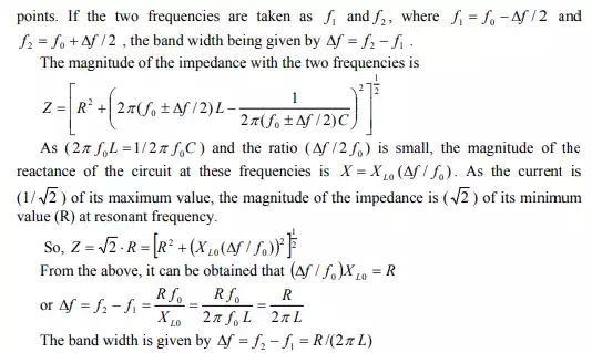
Example
A constant voltage of
frequency, 1 MHz is applied to a lossy inductor (r in series with L), in series
with a variable capacitor, C . The current drawn is maximum, when C = 400 pF;
while current is reduced to ![]() of the above value, when C =
450 pF. Find the values of r and L. Calculate also the quality factor of the
coil, and the bandwidth.
of the above value, when C =
450 pF. Find the values of r and L. Calculate also the quality factor of the
coil, and the bandwidth.
Circuit diagram
Solution
![]()