Capacitor and its behaviour
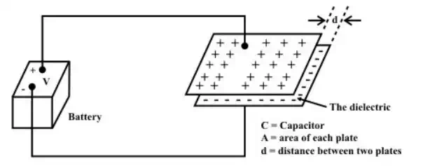
Figure shows a capacitor consists of two pieces of metal (the plates) separated from each other by a good insulator (the dielectric), with two wires (the leads) attached to the metal plates.
Charging of a capacitor
A battery is connected across the capacitor to transport charge from one plate to the other until the capacitor charge voltage build-up is equal to the battery voltage V . The voltage across the capacitor depends on how much charge was deposited on the plates and also how much capacitance the capacitor has. In other words, there is a relationship between the voltage (V ), charge (Q ) and capacitance (C ), they are related with a mathematical expression as
![]()
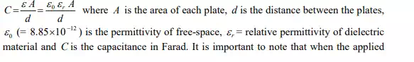
Where Q = magnitude of charge stored on each plate, V = voltage applied to the plates and the unit of capacitance is in Farad. Although the capacitance C of a capacitor is the ratio of charge per plate to the applied voltage, but it mainly depends on the physical dimension of the capacitor. If the area of the plates is larger, the more would be the amount of charge stored over the surface of the plates, resulting higher value of capacitance. On the other hand, if the spacing ‘d ’ between the plates is closer, accumulates more charge over the parallel plates and thus increases the value of the capacitance. The quality of dielectric material has an effect on capacitance between the plates. The good quality of dielectric material indicates that higher the permittivity, resulting greater the capacitance. The value of capacitance can be expressed in terms physical parameters of capacitor as,
voltage across the capacitor exceeds a certain value the dielectric material breaks down and loses it insulation property.
Continuity condition of capacitors
To find the current-voltage relationship of the capacitor, one can take the derivative of both sides of Equation.
![]()
The voltage-current relation can also be represented by another form as
![]()
be seen that when the voltage across a capacitor is not changing with time, or, in other words, the capacitor is fully charged and the current through the capacitor is zero. This means that the capacitor resembles as an open circuit and blocks the flow of current through the capacitor. Equation shows that an instantaneous (Δ t = 0 ) change in capacitance voltage must be accompanied by an infinite current that requiring an infinite power source. In practice, this situation will not occur in any circuits containing energy storing elements. Thus, the voltage across the capacitor (or electric charge q(t) )cannot change instantaneously ( i.e. ., Δ t= 0) , that is we cannot have any discontinuity in voltage across the capacitor.
Study of dc transients and steady state response of a series R-C circuit.
Ideal and real capacitors
An ideal capacitor has an infinite dielectric resistance and plates (made of metals) that have zero resistance. However, an ideal capacitor does not exist as all dielectrics have some leakage current and all capacitor plates have some resistance. A capacitor’s leakage resistance is a measure of how much charge (current) it will allow to leak through the dielectric medium. Ideally, a charged capacitor is not supposed to allow leaking any current through the dielectric medium and also assumed not to dissipate any power loss in capacitor plates resistance. Under this situation, the model as shown in fig.(a) represents the ideal capacitor. However, all real or practical capacitor leaks current to some extend due to leakage resistance of dielectric medium. This leakage resistance can be visualized as a resistance connected in parallel with the capacitor and power loss in capacitor plates can be realized with a resistance connected in series with capacitor. The model of a real capacitor is shown in fig.(b).
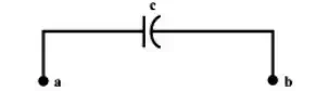
(a) Symbolic representation of an ideal capacitor
In present discussion, an ideal capacitor is considered to study the behaviour of dc transients in R – C circuit.
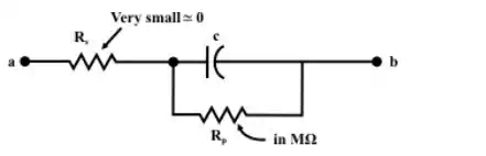
(b) Symbolic representation of a real capacitor