Study of dc transients and steady state response of a series R-L circuit.
Ideal Inductor: Fig.
shows an ideal inductor, like an ideal voltage source, has no resistance and it
is excited by a dc voltage source ![]()
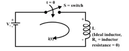
An ideal inductor connected to a constant voltage source
The switch ‘ S ’ is
closed at time ‘t = 0 ’ and assumed that the initial current flowing through
the ideal inductor i(0) just before closing the switch is equal to
zero. To find the system response ![]() one can apply KVL
around the closed path.
one can apply KVL
around the closed path.

Above Equation implies that the current through inductor increases with increase in time and theoretically it approaches to infinity as t → ∞ but in practice, this is not really the case.
Real or Practical inductor:
Below Fig shows a real or practical inductor has some resistance and it is exactly equal to the resistance of the wire used to wind the coil.
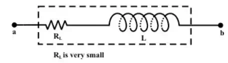
Representation of a practical inductor
Let us consider a
practical inductor is connected in series with an external resistance ![]() and
this circuit is excited with a dc voltage
and
this circuit is excited with a dc voltage ![]() as shown in fig.
as shown in fig.
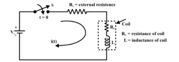
(a) A practical inductor connected to a constant voltage source
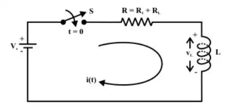
(b) Equivalent representation circuit
Our problem is to study the growth of current in the circuit through two stages, namely; (i) dc transient response (ii) steady state response of the system.