Thevenin’s and Norton’s theorems in the context of dc voltage and current sources acting in a resistive network
Introduction
A simple circuit as shown in fig is considered to illustrate the concept of equivalent circuit and it is always possible to view even a very complicated circuit in terms of much simpler equivalent source and load circuits. Subsequently the reduction of computational complexity that involves in solving the current through a branch for different values of load resistance ( RL ) is also discussed. In many applications, a network may contain a variable component or element while other elements in the circuit are kept constant. If the solution for current ( I ) or voltage (V ) or power ( P ) in any component of network is desired, in such cases the whole circuit need to be analysed each time with the change in component value. In order to avoid such repeated computation, it is desirable to introduce a method that will not have to be repeated for each value of variable component. Such tedious computation burden can be avoided provided the fixed part of such networks could be converted into a very simple equivalent circuit that represents either in the form of practical voltage source known as Thevenin’s voltage source.
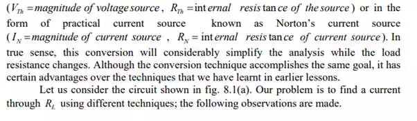
(a)A simple dc Network
Find
· Mesh current method needs 3 equations to be solved
· Node voltage method requires 2 equations to be solved
· Superposition method requires a complete solution through load resistance ( RL ) by considering each independent source at a time and replacing other sources by their internal source resistances.
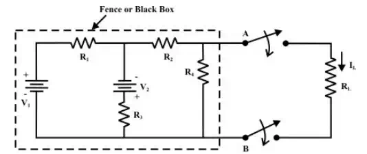
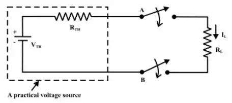
Suppose, if the value of RL is changed then the three (mesh current method) or two equations (node voltage method) need to be solved again to find the new current in RL . Similarly, in case of superposition theorem each time the load resistance RL is changed, the entire circuit has to be analysed all over again. Much of the tedious mathematical work can be avoided if the fixed part of circuit (fig. (a)) or in other words, the circuit contained inside the imaginary fence or black box with two terminals A & B , is replaced by the simple equivalent voltage source (as shown in fig. (b)) or current source (as shown in fig.(c)).
(b)circuit (a) is equivalently replaced by a simple practical voltage source
(c)circuit (a) is equivalently replaced by a simple practical current source
Thevenin’s Theorem:
Thevenin’s theorem states that any two output terminals ( A & B , shown in fig. (a)) of an active linear network containing independent sources (it includes voltage and current sources) can be replaced by a simple voltage source of magnitude VTh in series with a single resistor RTh (see fig.(d)) where RTh is the equivalent resistance of the network when looking from the output terminals A & B with all sources (voltage and current) removed and replaced by their internal resistances (see fig.(c)) and the magnitude of VTh is equal to the open circuit voltage across the A & B terminals. (The proof of the theorem will be given in section- L8. 5).