Application of superposition theorem
Example
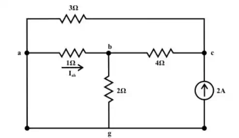
Consider the network
shown in fig. (a). Calculate ![]() and
and ![]() using
superposition theorem.
using
superposition theorem.
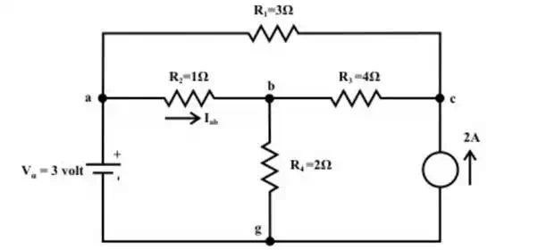
(a)
Solution:
Voltage Source Only (retain one source at a time):
First consider the
voltage source ![]() that acts only in the circuit
and the current source is replaced by its internal resistance ( in this case
internal resistance is infinite (
that acts only in the circuit
and the current source is replaced by its internal resistance ( in this case
internal resistance is infinite ( ![]() )). The corresponding
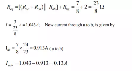
circuit diagram is shown in fig(b) and calculate the current flowing through
the ‘a-b’ branch.
)). The corresponding
circuit diagram is shown in fig(b) and calculate the current flowing through
the ‘a-b’ branch.

(b)
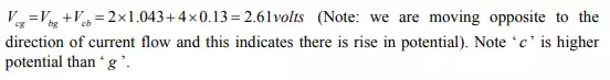
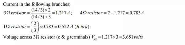
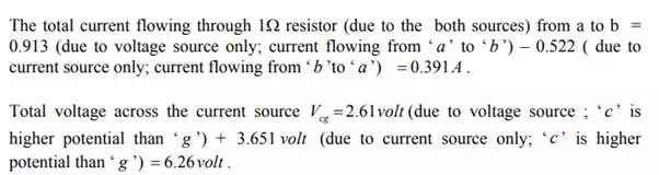
Voltage across c-g terminal :
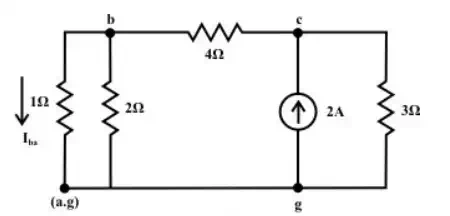
Current source only (retain one source at a time):
Now consider the current source Is = 2 A only and the voltage source is replaced by its internal resistance which is zero in the present case. The corresponding the simplified circuit diagram is shown below (see fig.(c)& fig(d)).
(c)
(d)
Example
For the circuit shown in
fig.(a), the value of ![]() are fixed.
are fixed.
![]()
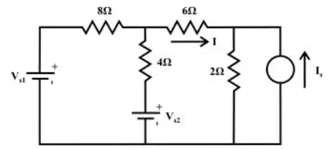
(a)
Solution:
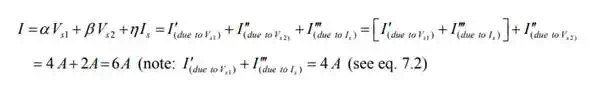
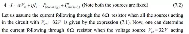
Let us assume that the current flowing 6Ω resistors due to the voltage and current sources are given by (assume circuit linearity)
![]() (7.1)
(7.1)
where the parametersα , , β and η represent the positive constant numbers. The parameters α and β are the total conductance of the circuit when each voltage source acting alone in the circuit and the remaining sources are replaced by their internal resistances. On the other hand, the parameter η represents the total resistance of the circuit when the current source acting alone in the circuit and the remaining voltage sources are replaced by their internal resistances. The expression (7.1) for current I is basically written from the concept of superposition theorem. From the first condition of the problem statement one can write an expression as (when the voltage source Vs1 and the current source s I acting jointly in the circuit and the other voltage source Vs2 is not present in the circuit.)
alone in the circuit and the other sources are replaced by their internal resistances. For the circuit shown in fig(b), the current delivered by the voltage source to the resistor is given by
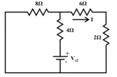
(b)
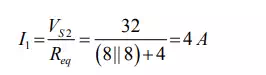 (7.3)
(7.3)
The current following through the 6Ω due to the voltage source only is VS 2 = 32V 2 A (flowing from left to right; i,e. in the direction as indicated in the figure (b)). Using equation (7.1), the total current I flowing the 6Ω resistor can be obtained as