AC/DC Converters
Introduction
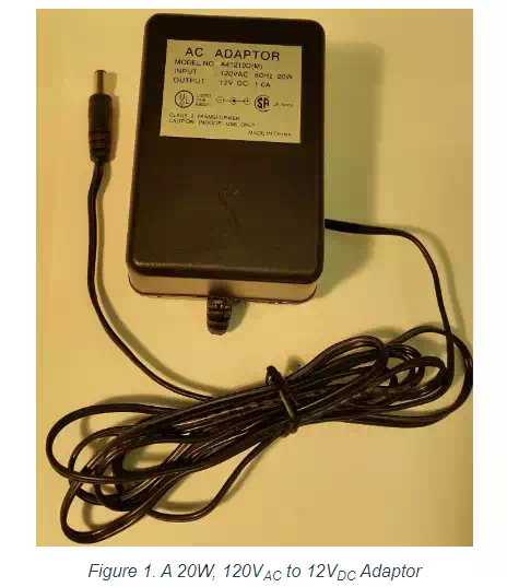
Wall adapter AC-DC converters (rectifiers) are such common devices that no one pays much attention to them unless they go missing and you can’t get the DC power that you need. On the surface, these rectifiers are fairly simple devices and I am sure that you have some level of understanding of how they work. Bear with me as I lay out the basic operation of AC-DC converters in this article. In subsequent articles, I will describe some of the more complicated topics related to AC-DC converters such as power factor, harmonic distortion, and reliability. The AC-DC converter in the image below expects an input of 120Vac at 60 Hz and provides an output of about 12VDC (it is an unregulated converter and so the output will vary with the load) and up to 1 Amp of current. The maximum input power is 20W.
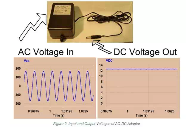
Let’s assume we know nothing about the way they work and only have the capability of measuring voltages into and out of the device. Measuring the input voltage and the output voltage would give the following results:
If we were just users of the wall adapter, that would be just about all that we need to know. The only other important thing would be to check the polarity of the plug and the socket to make sure they match (in this case, the center of the plug is positive). We are not just users of electronics though; we are curious electrical engineers, so let’s open up this converter to get a better idea of what is inside.
AC-DC Adaptor Circuit
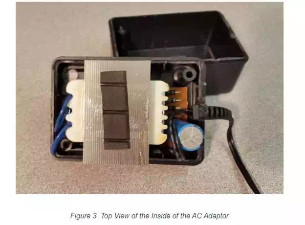
As you can see in figures 3 and 4, there is not much to this 120VAC to 12VDC adaptor.
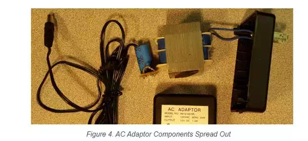
Looking at figure 4 and going from right (input) to left (output), there is a two-prong plug, connected to some wires going to the primary coils of a transformer. Then connected to the secondary of the transformer is a full bridge diode rectifier, followed by a filtering capacitor, and finally a center positive output jack. In the sections that follow the purpose of each of these components will be analyzed to show how the AC input voltage ultimately gets converted into a 12V DC voltage.
Transformer
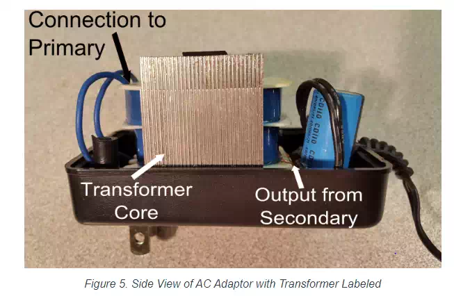
Figure 5 shows the same adaptor seen from the side. The blue wires on the right are the inputs from the two-prong wall connection and they connect directly to the primary of the transformer. The output from the secondary can be seen at the lower left of the transformer as two small copper wires. The purpose of the transformer is to step the AC voltage down from the 120VRMS from the wall outlet to a voltage that is closer to the required DC voltage.
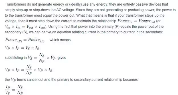
If you ignore all of the non-ideal properties of transformers, they are very simple devices. The general idea is that there are two (usually large) coils of wire that are electrically isolated, but magnetically coupled together. The input side of the transformer is called the primary and the output side is called the secondary. Alternating current passes through the primary coil which creates an alternating magnetic flux in the transformer core. This alternating magnetic flux in turn induces a voltage in the coils of the secondary. The ratio of the number of loops in the primary coil to the number of loops in the secondary coil is equal to the ratio of the input AC voltage to the output AC voltage. In equation form this relationship is:
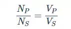
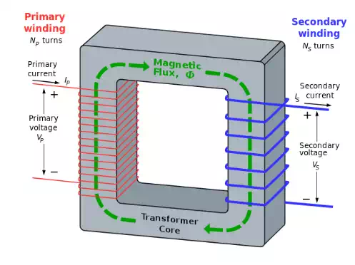
Figure 6 shows a cartoon representation of the coupling of the primary winding to the secondary winding through the transformer core. The geometry of the core of the AC adaptor from Figure 5 is different from this diagram's geometry, but the principle is the same.
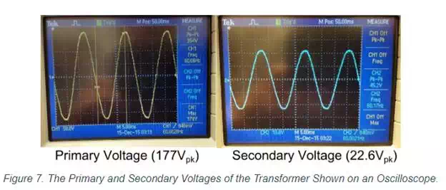
This figure shows that the primary voltage is 354Vp-p (177Vp or 125VRMS) and the output is 45.2Vp-p (22.6Vp or 16VRMS). The voltage ratio is about 7.8 (354/45.6) which means that the ratio of the number of turns in the primary to the secondary is also 7.8. There are a few non-ideal characteristics of transformers such as wire resistance, core saturation, magnetizing inductance and hysteresis that must be considered when more precise modeling of the system must be done. For the purposes of this article, we will just focus on the fact that a 177Vp AC voltage comes into the transformer and a 22.6Vp AC voltage goes out.