The Autotransformer
The primary and secondary windings of an Autotransformer are linked together both electrically and magnetically reducing the cost over conventional transformers
Unlike the previous voltage transformer which has two electrically isolated windings called: the primary and the secondary, an Autotransformer has only one single voltage winding which is common to both sides. This single winding is “tapped” at various points along its length to provide a percentage of the primary voltage supply across its secondary load. Then the autotransformer has the usual magnetic core but only has one winding, which is common to both the primary and secondary circuits. Therefore in an autotransformer the primary and secondary windings are linked together both electrically and magnetically. The main advantage of this type of transformer design is that it can be made a lot cheaper for the same VA rating, but the biggest disadvantage of an autotransformer is that it does not have the primary/secondary winding isolation of a conventional double wound transformer.
The section of winding designated as the primary part of the winding is connected to the AC power source with the secondary being part of this primary winding. An autotransformer can also be used to step the supply voltage up or down by reversing the connections. If the primary is the total winding and is connected to a supply, and the secondary circuit is connected across only a portion of the winding, then the secondary voltage is “stepped-down” as shown.
Autotransformer Design
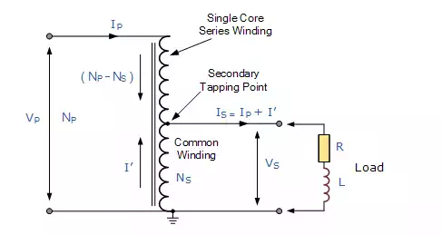
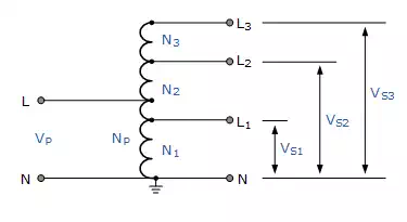
When the primary current IP is flowing through the single winding in the direction of the arrow as shown, the secondary current, IS, flows in the opposite direction. Therefore, in the portion of the winding that generates the secondary voltage, VS the current flowing out of the winding is the difference of IP and IS. The Autotransformer can also be constructed with more than one single tapping point. Auto-transformers can be used to provide different voltage points along its winding or increase its supply voltage with respect to its supply voltage VP as shown.
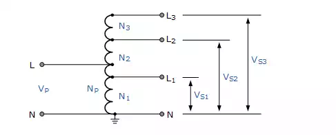
Autotransformer with Multiple Tapping Points
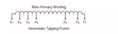
The standard method for marking an auto-transformer windings is to label it with capital (upper case) letters. So for example, A, B, Z etc to identify the supply end. Generally the common neutral connection is marked as N or n. For the secondary tapping’s, suffix numbers are used for all tapping points along the auto-transformers primary winding. These numbers generally start at number “1” and continue in ascending order for all tapping points as shown.
Autotransformer Terminal Markings
An autotransformer is used mainly for the adjustments of line voltages to either change its value or to keep it constant. If the voltage adjustment is by a small amount, either up or down, then the transformer ratio is small as VP and VS are nearly equal. Currents IP and ISare also nearly equal. Therefore, the portion of the winding which carries the difference between the two currents can be made from a much smaller conductor size, since the currents are much smaller saving on the cost of an equivalent double wound transformer. However, the regulation, leakage inductance and physical size (since there is no second winding) of an autotransformer for a given VA or KVA rating are less than for a double wound transformer. Autotransformer’s are clearly much cheaper than conventional double wound transformers of the same VA rating. When deciding upon using an autotransformer it is usual to compare its cost with that of an equivalent double wound type.
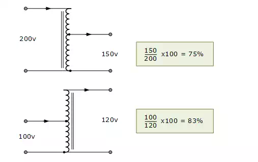
This is done by comparing the amount of copper saved in the winding. If the ratio “n” is defined as the ratio of the lower voltage to the higher voltage, then it can be shown that the saving in copper is: n*100%. For example, the saving in copper for the two autotransformers would be:
Autotransformer Example No1
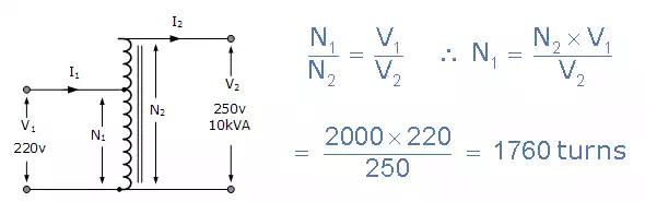
An autotransformer is required to step-up a voltage from 220 volts to 250 volts. The total number of coil turns on the transformer main winding is 2000. Determine the position of the primary tapping point, the primary and secondary currents when the output is rated at 10KVA and the economy of copper saved.
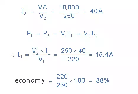
Thus the primary current is 45.4 amperes, the secondary current drawn by the load is 40 amperes and 5.4 amperes flows through the common winding. The economy of copper is 88%.
Disadvantages of an Autotransformer
· The main disadvantage of an autotransformer is that it does not have the primary to secondary winding isolation of a conventional double wound transformer. Then an autotransformer can not safely be used for stepping down higher voltages to much lower voltages suitable for smaller loads.
· If the secondary side winding becomes open-circuited, load current stops flowing through the primary winding stopping the transformer action resulting in the full primary voltage being applied to the secondary terminals.
· If the secondary circuit suffers a short-circuit condition, the resulting primary current would be much larger than an equivalent double wound transformer due to the increased flux linkage damaging the autotransformer.
· Since the neutral connection is common to both the primary and secondary windings, earthing of the secondary winding automatically Earth’s the primary as there is no isolation between the two windings. Double wound transformers are sometimes used to isolate equipment from earth.
The autotransformer has many uses and applications including the starting of induction motors, used to regulate the voltage of transmission lines, and can be used to transform voltages when the primary to secondary ratio is close to unity. An autotransformer can also be made from conventional two-winding transformers by connecting the primary and secondary windings together in series and depending upon how the connection is made, the secondary voltage may add to, or subtract from, the primary voltage.