Magnetic circuits and Core losses
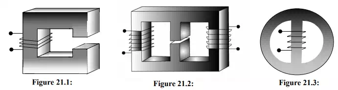
All of them have a magnetic material of regular geometric shape called core. A coil having a number of turns (= N) of conducting material (say copper) are wound over the core. This coil is called the exciting coil. When no current flows through the coil, we don’t expect any magnetic field or lines of forces to be present inside the core. However in presence of current in the coil, magnetic flux φ will be produced within the core. The strength of the flux, it will be shown, depends on the product of number of turns (N) of the coil and the current (i) it carries. The quantity Ni called mmf (magnetomotive force) can be thought as the cause in order to produce an effect in the form of flux φ within the core. Is it not somewhat similar to an electrical circuit problem where a voltage (emf) is applied (cause) and a current is produced (effect) in the circuit? Hence the term magnetic circuit is used in relation to producing flux in the core by applying mmf (= Ni). We shall see more similarities between an electrical circuit and a magnetic circuit in due course as we go along further. At this point you may just note that a magnetic circuit may be as simple as shown in figure 21.1 with a single core and a single coil or as complex as having different core materials, air gap and multiple exciting coils as in figure 21.2. After going through this lesson you will be able to do the following.
1. to distinguish between a linear and non linear magnetic circuit.
2. to draw the equivalent electrical circuit for a given magnetic circuit problem.
3. to calculate mean lengths of various flux paths.
4. to calculate the reluctances of the various flux paths for linear magnetic circuit problem.
5. to understand the importance of B-H characteristics of different materials.
6. how to deal with a non linear magnetic circuit problem using B-H characteristic of the materials.