Total Loss in a DC Generator:
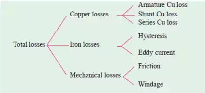
The various losses occurring in a generator can be divided as follows:
(a) Copper Losses
i) Armature copper loss = Ia2Ra where Ra = resistance of armature and interpoles and series field winding etc. This loss is about 30 to 40% of full-load losses.
ii) Field copper loss: In the case of shunt generators, it is practically constant and Ish 2Rsh (or VIsh). In the case of series generator, it is = Ise 2 Rse where Rse is resistance of the series field winding. This loss is about 20 to 30% of F.L. losses. iii) The loss due to brush contact resistance. It is usually included in the armature copper loss.
(b) Magnetic Losses (also known as iron or core losses): Due to the rotation of the iron core of the armature in the magnetic flux of the field poles, there are some losses taking place continuously in the core and are known as Iron Losses or Core Losses. Iron losses consist of (i) Hysteresis loss and (ii) Eddy Current loss.
(c) i) Hysteresis Loss (Wh): This loss is due to the reversal of magnetisation of the armature core. The loss depends upon the volume and grade of iron, maximum value of flux density Bmax and frequency of magnetic reversals. For normal flux densities (i.e. up to 1.5 Wb/m2 ), hysteresis loss is given by Steinmetz formula. According to this formula, Wh = ηB max 1.6 f V (watt), where Bmax = maximum flux density, V = volume of the core in m3 , η = Steinmetz hysteresis coefficient. Value of η for: Good dynamo sheet steel=502 J/m3 , Silicon steel=191 J/m3 , Hard Cast steel=7040 J/m3 , Caststeel= 750−3000 J/m3 and Cast iron =2700−4000 J/m3 . For reducing the hysteresis loss, those metals are chosen for the armature core which have a low hysteresis coefficient. Generally, special silicon steels such as alloys are used which not only have a low hysteresis coefficient but which also possess high electrical resistivity.
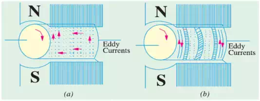
ii) Eddy Current Loss (We): When the armature core rotates, it also cuts the magnetic flux. Hence, an emf is induced in the body of the core according to the laws of electromagnetic induction. This emf though small, sets up large current in the body of the core due to its small resistance. This current is known as eddy current. The power loss due to the flow of this current is known as eddy current loss. This loss would be considerable if solid iron core were used. In order to reduce this loss and the consequent heating of the core to a small value, the core is built up of thin laminations, which are stacked and then riveted at right angles to the path of the eddy currents. These core laminations are insulated from each other by a thin coating of varnish. Eddy current loss (We) is given by the following relation:
![]()
where Bmax=maximum flux density, f=frequency of magnetic reversals, t=thickness of each lamination and V = volume of armature core.
(c) Mechanical Losses: These consist of:
i) Friction loss at bearings and commutator
(ii) air-friction or windage loss of rotating armature. Mechanical losses are about 10 to 20% of F.L. Losses. The total losses in a dc generator are summarized below:
Magnetic and mechanical losses are collectively known as Stray Losses Wstray = WIron +Wmech. field Cu loss is constant for shunt and compound generators. Hence, stray losses and shunt Cu loss are constant in their case. These losses are together known as standing or constant losses Wc . Hence, for shunt and compound generators: Total loss=armature copper loss+Wc =Ia 2Ra+Wc=(I+Ish) 2Ra + Wc Armature Cu loss Ia 2Ra is known as variable loss because it varies with the load current. Total loss = variable loss + constant losses (Wc)
Various power stages in the case of a dc generator are shown below :
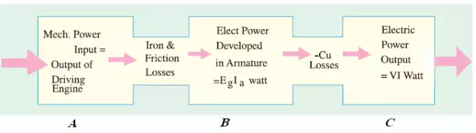
Following are the three generator efficiencies:
1. Mechanical Efficiency: ηm=total power generated in armature/mechanical input power
2. Electrical Efficiency: ηe=output electrical power/ total power generated in armature
3. Overall or Commercial Efficiency ηc = output electrical power / mechanical input power