DC GENERATORS
Generator Principle: An electrical generator is a machine which converts mechanical energy into electrical energy. The energy conversion is based on the principle of the production of dynamically induced emf, where a conductor cuts magnetic flux, dynamically induced emf is produced in it according to Faraday’s Laws of electromagnetic Induction. This emf causes a current to flow if the conductor circuit is closed. Hence, two basic essential parts of an electrical generator are (i) a magnetic field and (ii) a conductor or conductors which can so move as to cut the flux. The following figure shows a single-turn rectangular copper coil rotating about its own axis in a magnetic field provided by either permanent magnets or electromagnets. The two ends of the coil are joined to two slip-rings ‘a’ and ‘b’ which are insulated from each other and from the central shaft. Two collecting brushes (of carbon or copper) press against the slip-rings. Their function is to collect the current induced in the coil and to convey it to the external load resistance R. The rotating coil may be called ‘armature’ and the magnets as ‘field magnets’.
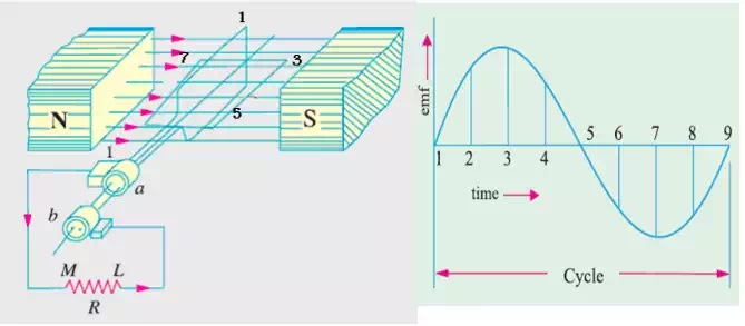
As the coil rotates in clock-wise direction and assumes successive positions in the field the, flux linked with it changes. Hence, an emf is induced in it which is proportional to the rate of change of flux linkages (e = Ndf /dt)
· When the plane of the coil is at right angles to lines of flux i.e. when it is in position 1, then flux linked with the coil is maximum, but rate of change of flux linkages is minimum. Hence, there is no induced emf in the coil.
· As the coil continues rotating further, the rate of change of flux linkages (and hence induced emf in it) increases, till position 3 is reached where θ = 90º, the coil plane is horizontal i.e. parallel to the lines of flux. The flux linked with the coil is minimum but rate of change of flux linkages is maximum. Hence, maximum emf is induced in the coil at this position. v From 90º to 180º, the flux linked with the coil gradually increases but the rate of change of flux linkages decreases. Hence, the induced emf decreases gradually till in position 5 of the coil, it is reduced to zero value.
· From 180º to 360º, the variations in the magnitude of emf are similar to those in the first half revolution. Its value is maximum when coil is in position 7 and minimum when in position 1. But it will be found that the direction of the induced current is the reverse of the previous direction of flow.
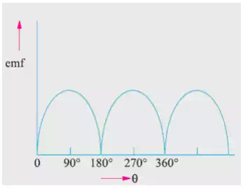
For making the flow of current unidirectional in the external circuit, the slip-rings are replaced by split-rings. The split-rings are made out of a conducting cylinder which is cut into two halves or segments insulated from each other by a thin sheet of mica or some other insulating material. As before, the coil ends are joined to these segments on which rest the carbon or copper brushes. It is seen that in the first half revolution current flows along (ABMLCD) i.e. the brush No.1 in contact with segment ‘a’ acts as the positive end of the supply and ‘b’ as the negative end. In the next half revolution, the direction of the induced current in the coil has reversed. But at the same time, the positions of segments ‘a’ and ‘b’ have also reversed with the result that brush No.1 comes in touch with the segment which is positive i.e. segment ‘b’ in this case. Hence, current in the load resistance again flows from M to L. The waveform of the current through the external circuit is as shown in below. This current is unidirectional but not continuous like pure direct current.
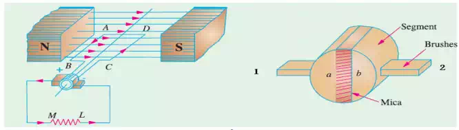
The position of brushes is so arranged that the change over of segments ‘a’ and ‘b’ from one brush to the other takes place when the plane of the rotating coil is at right angles to the plane of the lines of flux. It is so because in that position, the induced emf in the coil is zero. The current induced in the coil sides is alternating as before. It is only due to the rectifying action of the split-rings (also called commutator) that it becomes unidirectional in the external circuit.
Practical Generator: The actual generator which consists of the following essential parts:
1.Magnetic Frame or Yoke
2.Pole-Cores and Pole-Shoes
3.Pole Coils or Field Coils
4.Armature Core
5.Armature Windings or Conductors
6.Commutator
7.Brushes
8.Bearings.
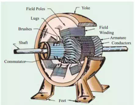
Yoke: The outer frame or yoke serves double purpose: (i) It provides mechanical support for the poles and acts as a protecting cover for the whole machine. (ii) It carries the magnetic flux produced by the poles. In small generators where cheapness rather than weight is the main consideration, yokes are made of cast iron. But for large machines usually cast steel or rolled steel is employed.
Pole Cores and Pole Shoes: The field magnets consist of pole cores and pole shoes. The pole shoes serve two purposes: (i) They spread out the flux in the air gap and also, being of larger cross-section, reduce the reluctance of the magnetic path. (ii) They support the exciting coils (or field coils) as shown below.
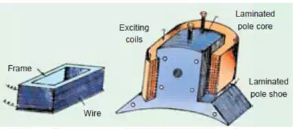
Pole Coils: The field coils or pole coils, which consist of copper wire or strip, are former-wound for the correct dimension. Then, the former is removed and wound coil is put into place over the core. When current is passed through these coils, they electromagnetise the poles which produce the necessary flux that is cut by revolving armature conductors.
Armature Core: It houses the armature conductors or coils and causes them to rotate and hence cut the magnetic flux of the field magnets. In addition to this, its most important function is to provide a path of very low reluctance to the flux through the armature from a N-pole to a S-pole. It is cylindrical or drum-shaped and is built up of usually circular sheet steel discs or laminations approximately 0.5 mm thick. The slots are either die-cut or punched on the outer periphery of the disc and the keyway is located on the inner diameter as shown. In small machines, the armature stampings are keyed directly to the shaft. Usually, these laminations are perforated for air ducts which permit axial flow of air through the armature for cooling purposes.
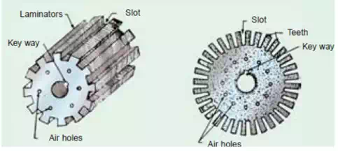
The purpose of using laminations is to reduce the loss due to eddy currents. Thinner the laminations, greater is the resistance offered to the induced emf, smaller the current and hence lesser the I2 R loss in the core.
Armature Windings: The armature windings are usually former-wound. These are first wound in the form of flat rectangular coils and are then pulled into their proper shape in a coil puller. Various conductors of the coils are insulated from each other. The conductors are placed in the armature slots which are lined with tough insulating material. This slot insulation is folded over above the armature conductors placed in the slot and is secured in place by special hard wooden or fiber wedges.
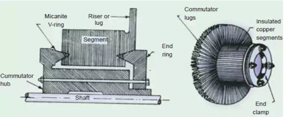
Commutator: The functions of the commutator are to facilitate collection of current from the armature conductors, and to convert the alternating current induced in the armature conductors into unidirectional current in the external load circuit. It is of cylindrical structure and is built up of wedge-shaped segments of high-conductivity hard-drawn or drop forged copper. These segments are insulated from each other by thin layers of mica. The number of segments is equal to the number of armature coils. Each commutator segment is connected to the armature conductor by means of a copper lug or riser. To prevent them from flying out under the action of centrifugal forces, the segments have V-grooves, these grooves being insulated by conical micanite rings.
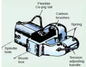
Brushes and Bearings: The brushes, whose function is to collect current from commutator, are usually made of carbon or graphite and are in the shape of a rectangular block. These brushes are housed in brush-holders, the brush-holder is mounted on a spindle and the brushes can slide in the rectangular box open at both ends. The brushes are made to bear down on the commutator by a spring. A flexible copper pigtail mounted at the top of the brush conveys current from the brushes to the holder. The number of brushes per spindle depends on the magnitude of the current to be collected from the commutator.
Because of their reliability, ball-bearings are frequently employed, though for heavy duties, roller bearings are preferable. The ball and rollers are generally packed in hard oil for quieter operation and for reduced bearing wear, sleeve bearings are used which are lubricated by ring oilers fed from oil reservoir in the bearing bracket.
Armature Windings: the following terms is used in connection with armature winding:
· Pole-pitch: the distance between two adjacent poles. It is equal to the number of armature conductors (or armature slots) per pole. If there are 48 conductors and 4 poles, the pole pitch is 48/4 = 12.
· Conductor: The length of a wire lying in the magnetic field and in which an emf is induced, is called a conductor (or inductor) as, for example, length AB or CD in the following figure.
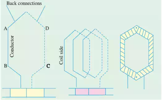
· Coil and Winding Element: the two conductors AB and CD along with their end connections constitute one coil of the armature winding. The coil may be single turn coil or multi-turn coil. Multi-turn coil may have many conductors per coil side. The group of wires or conductors constituting a coil side of a multi-turn coil is wrapped with a tape as a unit and is placed in the armature slot. Since the beginning and the end of each coil must be connected to a commutator bar, there are as many commutator bars as coils for both the lap and wave windings. The side of a coil (1-turn or multi-turn) is called a winding element. The number of winding elements is twice the number of coils.
· Coil-span or Coil-pitch (YS): It is the distance, measured in terms of armature slots (or armature conductors) between two sides of a coil. If the pole span or coil pitch is equal to the pole pitch. Then winding is called full-pitched. It means that coil span is 180 electrical degrees. In this case, the coil sides lie under opposite poles, hence the induced emfs in them are additive. Therefore, maximum emf is induced in the coil as a whole, it being the sum of the emfs induced in the two coil sides. If the coil span is less than the pole pitch, then the winding is fractional-pitched. In this case, there is a phase difference between the emfs. In the two sides of the coil. Hence, the total emf round the coil which is the vector sum of emfs in the two coil sides is less in this case as compared to that in the first case.
· Back Pitch (YB): The distance, measured in terms of the armature conductors, which a coil advances on the back of the armature is called back pitch.
· Front Pitch (YF): The number of armature conductors or elements spanned by a coil on the front (or commutator end of an armature) is called the front pitch.
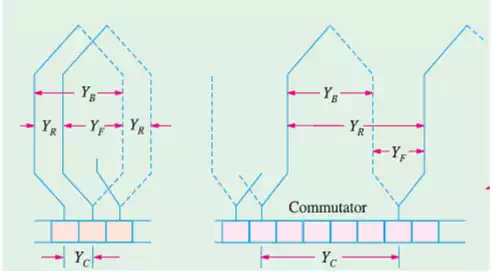
· Resultant Pitch (YR): It is the distance between the beginning of one coil and the beginning of the next coil to which it is connected.
· Commutator Pitch (Yc): It is the distance (measured in commutator bars or segments) between the segments to which the two ends of a coil are connected.
· Single-layer Winding: It is that winding in which one conductor or one coil side is placed in each armature slot. Such a winding is not much used.
· Two-layer Winding: In this type of winding, there are two conductors or coil sides per slot arranged in two layers. Usually, one side of every coil lies in the upper half of one slot and other side lies in the lower half of some other slot. Such windings in which two coil sides occupy each slot are most commonly used for all medium-sized machines. Sometimes 4 or 6 or 8 coil sides are used in each slot in several layers because it is not practicable to have too many slots. · Multiplex Winding: In such windings, there are several sets of completely closed and independent windings. If there is only one set of closed winding, it is called simplex wave winding. If there are two such windings on the same armature, it is called duplex winding and so on. The multiplicity affects a number of parallel paths in the armature. For a given number of armature slots and coils, as the multiplicity increases, the number of parallel paths in the armature increases thereby increasing the current rating but decreasing the voltage rating.