Basic Operation of The Synchronous Machine
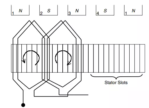
Fig. 1.21 “Developed” view of a four-pole stator, showing the slots, the poles, and a section of the winding. The section shown is of one of the three phases. It can be readily seen that the winding runs clockwise under a north pole, and counterclockwise under a south pole. This pattern repeats itself until the winding covers the four poles. A similar pattern is followed by the other two phases, but located at 120 electrical degrees apart.
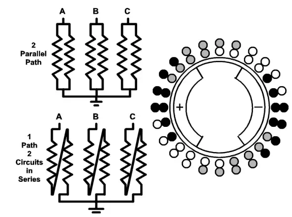
Fig. 1.22 Schematic view of a two-pole generator with two possible winding configurations: (1) A two parallel circuits winding, (2) A two series connected circuits per phase. On the right, the three phases are indicated by different tones. Note that, some slots only have coils belonging to the same phase, while in others, coils belonging to two phases share the slot.
All large turbogenerators are three-phase machines. Thus the best place to start describing the operation of a three-phase synchronous machine is a description of its magnetic field.
Earlier we described how a current flowing through a conductor produces a magnetic field associated with that current. It was also shown that by coiling the conductor, a larger field is obtained without increasing the current’s magnitude. Recall that if the three phases of the winding are distributed at 120 electrical degrees apart, three balanced voltages are generated, creating a three-phase system.
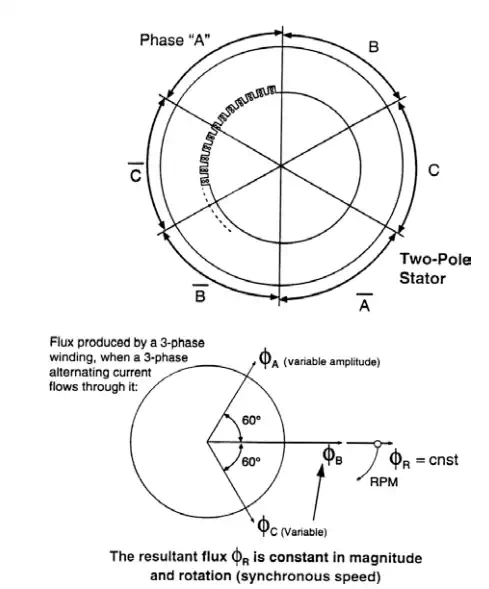
Now a new element can be brought into the picture. By a simple mathematical analysis it can be shown that if three balanced currents (equal magnitudes and 120 electrical degrees apart) flow in a balanced three-phase winding, a magnetic field of constant magnitude is produced in the airgap of the machine. This magnetic field revolves around the machine at a frequency equal to the frequency of the currents flowing through the winding (see Fig. 1.23). The importance of a three-phase system creating a constant field cannot be stressed enough. The constant magnitude flux allows hundred of megawatts of power to be transformed inside an electric machine from electrical to mechanical power, and vice versa, without major mechanical limitations. It is important to remember that a constant magnitude flux produces a constant-magnitude torque. Now try to imagine the same type of power being transformed under a pulsating flux (and therefore pulsating torque), which is tremendously difficult to achieve.
It is convenient to introduce the fundamental principles describing the operation of a synchronous machine in terms of an ideal cylindrical-rotor machine connected to an infinite bus. The infinite bus represents a busbar of constant voltage, which can deliver or absorb active and reactive power without any limitations. The ideal machine has zero resistance and leakage reactance, infinite permeability, and no saturation, as well as zero reluctance torque.
The production of torque in the synchronous machine results from the natural tendency of two magnetic fields to align themselves. The magnetic field produced by the stationary armature is denoted as φs. The magnetic field produced by the rotating field is φf. The resultant magnetic field is
φr = φs + φf
The flux φr is established in the airgap (or gasgap) of the machine. (Bold symbols indicate vector quantities.)
When the torque applied to the shaft equals zero, the magnetic fields of the rotor and the stator become perfectly aligned. The instant torque is introduced to the shaft, either in a generating mode or in a motoring mode, a small angle is created between the stator and rotor fields. This angle (λ) is called the torque angle of the machine.