Principles of Construction
Synchronous machines come in all sizes and shapes, from the miniature permanent magnet synchronous motor in wall-clocks, to the largest steam-turbinedriven generators of up to about 1500 MVA. Synchronous machines are one of two types: the stationary field or the rotating dc magnetic field.
The stationary field synchronous machine has salient poles mounted on the stator—the stationary member. The poles are magnetized either by permanent magnets or by a dc current. The armature, normally containing a three-phase winding, is mounted on the shaft. The armature winding is fed through three sliprings (collectors) and a set of brushes sliding on them. This arrangement can be found in machines up to about 5 kVA in rating. For larger machines—all those covered in this book—the typical arrangement used is the rotating magnetic field.
The rotating magnetic field (also known as revolving-field) synchronous machine has the field-winding wound on the rotating member (the rotor), and the armature wound on the stationary member (the stator). A dc current, creating a magnetic field that must be rotated at synchronous speed, energizes the rotating field-winding. The rotating field winding can be energized through a set of slip rings and brushes (external excitation), or from a diode-bridge mounted on the rotor (self-excited). The rectifier-bridge is fed from a shaft-mounted alternator, which is itself excited by the pilot exciter. In externally fed fields, the source can be a shaft-driven dc generator, a separately excited dc generator, or a solid-state rectifier. Several variations to these arrangements exist.
The stator core is made of insulated steel laminations. The thickness of the laminations and the type of steel are chosen to minimize eddy current and hysteresis losses, while maintaining required effective core length and minimizing costs. The core is mounted directly onto the frame or (in large two-pole machines) through spring bars. The core is slotted (normally open slots), and the coils making the winding are placed in the slots. There are several types of armature windings, such as concentric windings of several types, cranked coils, split windings of various types, wave windings, and lap windings of various types. Modern large machines typically are wound with double-layer lap windings.
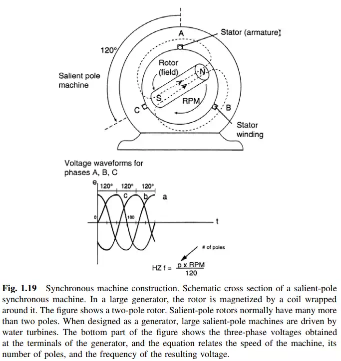
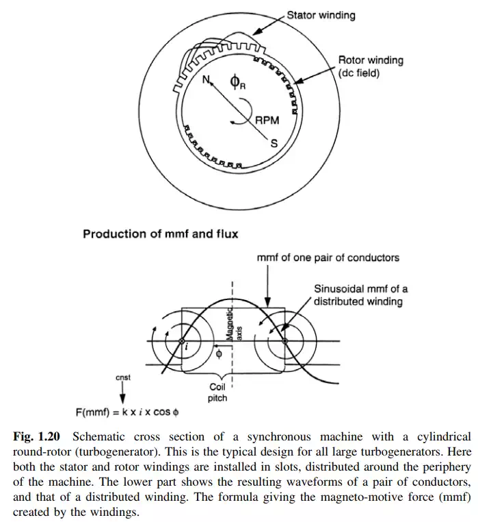
The rotor field is either of salient-pole (Fig. 1.19) or non-salient-pole construction, also known as round rotor or cylindrical rotor (Fig. 1.20). Non-salient-pole (cylindrical) rotors are utilized in two- or four-pole machines, and, very seldom, in six-pole machines. These are typically driven by steam or combustion turbines. The vast majority of salient-pole machines have six or more poles. They include all synchronous hydrogenerators, almost every synchronous condenser, and the overwhelming majority of synchronous motors.
Non-salient-pole rotors are typically machined out of a solid steel forging. The winding is placed in slots machined out of the rotor body and retained against the large centrifugal forces by metallic wedges, normally made of aluminum or steel. The retaining rings restrain the end part of the windings (end-windings). In the case of large machines, the retaining rings are made out of steel.
Large salient-pole rotors are made of laminated poles retaining the winding under the pole head. The poles are keyed onto the shaft or spider-and-wheel structure. Salient-pole machines have an additional winding in the rotating member. This winding, made of copper bars short-circuited at both ends, is embedded in the head of the pole, close to the face of the pole. The purpose of this winding is to start the motor or condenser under its own power as an induction motor, and take it unloaded to almost synchronous speed, when the rotor is “pulled in” by the synchronous torque. The winding also serves to damp the oscillations of the rotor around the synchronous speed, and is therefore named the damping-winding (also known as amortisseurs or damper-windings).