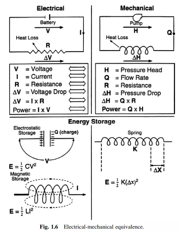
Electrical—Mechanical Equivalence
There is an interesting equivalence between the various parameters describing electrical and mechanical forms of energy. People with either electrical or mechanical backgrounds find this equivalence useful to the understanding of the physical process in either form of energy. Figure 1.6 describes the various forms of electrical-mechanical equivalence.
Alternated Circuits (Ac)
As it will be shown later, alternators operate with both alternating (ac) and direct-current (dc) electric power. The dc can be considered a particular case of the general ac, with frequency equal to zero.
The frequency of an alternated circuit is measured by the number of times the currents and/or voltages change direction (polarity) in a unit of time. The Hertz is the universally accepted unit of frequency, and measures cycles per second. One
Hz equals one cycle per second. Alternated currents and voltages encountered in the world of industrial electric power are for all practical purposes of constant frequency. This is important because periodic systems, namely systems that have constant frequency, allow the currents and voltages to be represented by phasors.
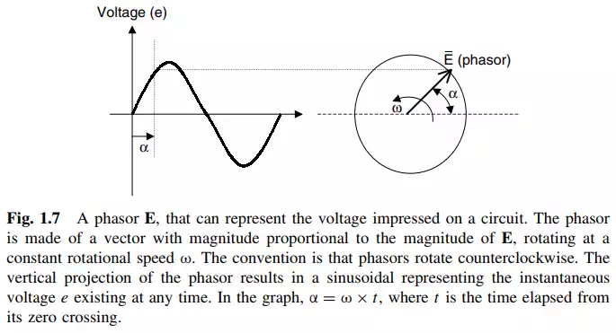
A phasor is a rotating vector. The benefit of using phasors in electrical engineering analysis is that it greatly simplifies the calculations required to solve circuit problems.
Figure 1.7 depicts a phasor of magnitude E, and its corresponding sinusoidal trace representing the instantaneous value of the quantity e. The magnitude E represents the maximum value of e.
When a sinusoidal voltage is applied to a closed circuit, a current will flow in it. After a while the current will have a sinusoidal shape (this is called the steadystate current component) and the same frequency as the voltage. An interesting phenomenon in periodic circuits is that the resulting angle between the applied voltage and the current depends on certain characteristics of the circuit. These characteristics can be classified as being resistive, capacitive, and inductive. The angle between the voltage and the current in the circuit is called the power angle. The cosine of the same angle is called the power factor of the circuit, or for short, the PF.
Note: As it will be shown latter, in synchronous machines the term power angle is used to identify a different concept. To avoid confusion, in this book the angle between the current and the voltage in the circuit will therefore be identified by the “power factor.”
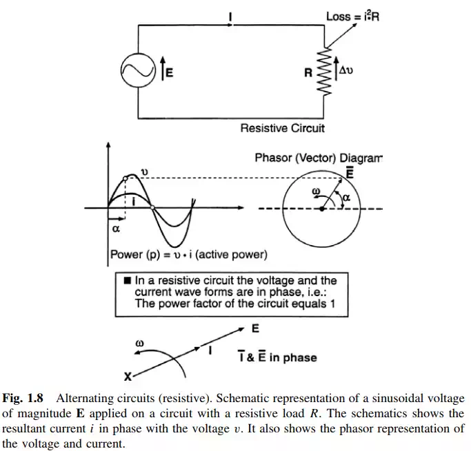
In the case of a circuit having only resistances, the voltages and currents are in phase, meaning the angle between them equals zero. Figure 1.8 shows the various parameters encountered in a resistive circuit. It is important to note that resistances have the property of generating heat when a current flows through them. The heat generated equals the square of the current times the value of the resistance. When the current is measured in amperes and the resistance in ohms, the resulting power dissipated as heat is given in watts. In electrical machines this heat represents a loss of energy. It will be shown later that one of the fundamental requirements in designing an electric machine is the efficient removal of these resistive losses, with the purpose of limiting the undesirable temperature rise of the internal components of the machine.
In resistive circuits the instantaneous power delivered by the source to the load equals the product of the instantaneous values of the voltage and the current. When the same sinusoidal voltage is applied across the terminals of a circuit with capacitive or inductive characteristics, the steady-state current will exhibit an angular (or time) displacement vis-a-vis the driving voltage. The magnitude
of the angle (or power factor) depends on how capacitive or inductive the load is. In a purely capacitive circuit, the current will lead the voltage by 90◦ , while in a purely inductive one, the current will lag the voltage by 90◦.
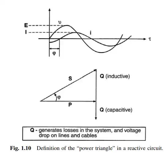
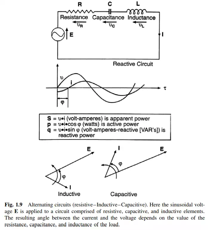
A circuit that has capacitive or inductive characteristics is referred to as being a reactive circuit. In such a circuit, the following parameters are defined:
S: The apparent power → S = E × I, given in units of volt-amperes or VA.
P: The active power → P = E × I × cos ϕ, where ϕ is the power angle of the circuit.
P is given in units of watts. Q: The reactive power → Q = E × I × sin ϕ, given in units of volt-amperes-reactive or VAR.
The active power P of a circuit indicates a real energy flow. This is power that may be dissipated on a resistance as heat, or may be transformed into mechanical energy, as it will be shown later. However, the use of the word “power” in the name of S and Q has been an unfortunate choice that has resulted in confounding most individuals without an electrical engineering background for many years. The fact is that apparent power and reactive power does not represent any measure of real energy. They do represent the reactive characteristic of a given load or circuit, and the resulting angle (power factor) between the current and voltage. This angle between voltage and current significantly affects the operation of an electric machine, as it will be discussed later.
For the time being let us define another element of ac circuit analysis: the power triangle. From the relationships shown above among S, P, Q, E, I, and ϕ, it can be readily shown that S, P, and Q form a triangle. By convention, Q is shown as positive (above the horizontal), when the circuit is inductive, and vice versa when capacitive (see Fig. 1.10).