Magnetic Circuit Calculations:
Normally magnetic circuit calculations involve two types of problems. In the first type of problem it is required to determine the excitation (mmf) needed to establish a desired flux or flux density at a given point in a magnetic circuit. This is the normal case in designing electromechanical devices and is a straight forward problem. In the second category the flux (or flux density) is unknown and is required to be determined for a. given geometry of the magnetic circuit and specified mmf. This kind of problem arises in magnetic amplifiers wherein this resultant flux is required to be determined owing to the given excitation on one or more control windings. A little thought will reveal that there is no direct analytical solution to this problem because of the non-linear B-H characteristic of the magnetic material. Graphical/ numerical techniques have to be used in obtaining the solution of this problem.
Leakage Flux
In all practical Magnetic Circuit Calculations, most of the flux is confined to the intended path by use of magnetic cores but a small amount of flux always leaks through the surrounding air. This stray flux as already stated is called the leakage flux. Leakage is characteristic of all magnetic circuits and can never be fully eliminated. Calculations concerning the main Magnetic Circuit Calculations are usually carried out with the effect of leakage flux either ignored or empirically accounted for. Special studies of leakage must be made for ac machines and transformers since their performance is affected by it.
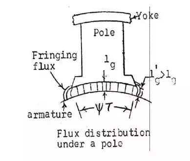
Fringing
At an air-gap in a magnetic core, the flux fringes out into neighbouring air paths as shown in Fig. 2.5. These being of reluctance comparable to that of the gap. The result is nonuniform flux density in the air-gap (decreasing outward), enlargement of the effective air-gap area and a decrease in the average gap flux density. The fringing effect also disturbs the core flux pattern to some depth near the gap. The effect of fringing increases with the air-gap length. Corrections for fringing in short gaps (as used in machines) are empirically made by adding one gap length to each of the two

dimensions making up its area. For the example of the core with the air-gap previously presented, the gap reluctance would now be given by

which will be less than the previous value as Ag > A.
It can be shown theoretically that the magnetic flux leaves and enters the surface of an infinitely permeable material normally. This will be nearly so in ferromagnetic materials which have high permeability. In electric machines a small amount of the tangential flux component present at iron surfaces will be neglected.
Stacking Factor
Magnetic cores are made up of thin, lightly insulated (coating of varnish) laminations to reduce power loss in cores due to the eddy-current phenomenon. As a result, the net cross-sectional area of the core occupied by the magnetic material is less than its gross cross-section; their ratio (less than unity) being known as the stacking factor. Depending upon the thickness of laminations, stacking factor may vary from 0.5-0.95, approaching unity as the lamination thickness increases.
Magnetic circuit calculations
The different parts of the dc machine magnetic circuit / pole are yoke, pole, air gap, armature teeth and armature core. Therefore, the ampere magnetic circuit is the sum of the ampere That is,
AT / pole = ATy + ATp+ ATg
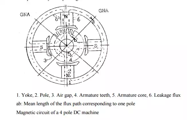
1. Yoke,
2. Pole,
3. Air gap,
4. Armature teeth,
5. Armature core,
6. Leakage flux ab: Mean length of the flux path corresponding to one pole
Magnetic circuit of a 4 pole DC machine
Note: Leakage factor or Leakage coefficient LC.
All the flux produced by the pole will not pass through the desired path i.e., air gap. Some of the flux produced by the pole will be leaking away from the air gap. The flux that passes through the air gap and cut by the armature conductors is the useful flux and that flux that leaks away from the desired path is the leakage flux
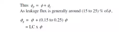
where LC is the Leakage factor or Leakage coefficient and lies between (1.15 to 1.25). Magnitude of flux in different parts of the magnetic circuit
a) Flux in the yoke
b) Flux in the pole
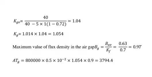
c) Flux in the air gap
d)Flux in the armature teeth
e) Flux in the armature core
Reluctance of the air gap
Where
lg = Length of air gap
t = Width (pole arc) over which the flux is passing in the air gap
L = Axial length of the armature core
y t L = Air gap area / pole over which the flux is passing in the air gap