An Introduction to
Rectifier Circuits
An important
application of the diode is one that takes place in the design of the rectifier
circuit. Simply put, this circuit converts alternating current (AC) to direct
current (DC). This is an essential circuit in AC-to-DC power-supply design.
The Rectifier Circuit
In order to power any
circuit, a power supply is needed; and if you want to power electronic devices
from an AC supply, a rectifier is needed.
Figure 1.1 illustrates a
schematic diagram of a DC power supply. There is a 120 V (rms),
60 Hz AC line that feeds the power supply, which delivers a voltage VO to the electronic circuit (load
block). VO must
be a stable DC voltage to ensure that the electronic circuitry functions
correctly.
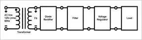
Figure 1.1
Looking at the diagram, first
we see the transformer. This transformer is a step-down transformer that “steps
down” the high AC input voltage to a lower AC voltage to be inputted into the
rectifier. This transformer consists of two separate coil windings (primary and
secondary windings) that have a different number of turns, N1 for the primary and N2 for the secondary. Thus, the AC
voltage vS can be written as 120(N2/N1) V (rms) and is measured between the two
terminals of the secondary winding.
Next, the diode rectifier
converts the AC voltage vS to a DC voltage. This voltage will
exhibit large variations and thus will not be suitable for electronic
circuitry. A filter is used to smooth out these variations.
Even after filtering, though,
the voltage will exhibit small variations known as ripple. Consequently, a
voltage regulator is used to greatly reduce the ripple and establish a reliable
DC supply rail.
Half-Wave Rectifier Circuit
The half-wave rectifier
eliminates the negative portions of the input sinusoid. In Figure 1.2 (A), the
half-wave rectifier is illustrated. In this article, we will use the constant
voltage drop (CVD) model of a diode owing to its simplicity. From this model,
we are provided with
v0=0v0=0
when
vS<VDvS<VD
Equation 1.1 (A)
v0=vS−VDv0=vS−VD
when
vS≥VDvS≥VD
Equation 1.1 (B)
where VD ≈
0.7 V. The above equations lead to the transfer characteristic illustrated in
Figure 1.2 (B). Figure 1.2 (C) illustrates the voltage output that is provided
when the input voltage vS is sinusoidal.
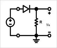
Figure 1.2 (A) The half-wave
rectifier
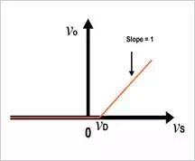
Figure 1.2 (B) Transfer characteristics
of the rectifier circuit
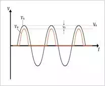
Figure 1.2 (C) Input and output waveforms
When determining which diodes
to use in a rectifier circuit, there are two things to take into consideration:
1) the diode's ability to handle current, which must be chosen based on the
largest current that is expected to be conducted by the diode, and 2) the peak
inverse voltage (PIV), which is the highest reverse voltage to which the diode
will be subjected; the diode must be able to withstand the PIV. Looking at
Figure 1.2 (A), we can observe that when the voltage vS is negative, the diode will be cut
off and the voltage vOwill have a value of zero, leading to a
reverse voltage across the diode of magnitude vS. Thus, the PIV is the peak ofvS:
PIV = VS
Equation 1.2
where VS (with an uppercase V) represents
the peak amplitude of the input sinusoid.
One thing worth noting is
that the circuit clearly will not operate effectively when the input sinusoid's
peak amplitude is not significantly higher than VD. For example, a sinusoidal input with
peak amplitude of 200 mV will not be rectified at all because the diode will
never "turn on," i.e., it will never conduct significant amounts of
current.
Full-Wave Rectifier Circuit
Unlike the half-wave
rectifier, the full-wave rectifier can utilize both the negative and the
positive portion of the AC input voltage. In order to achieve a unipolar
output, the negative portion of the sinusoidal waveform must be inverted. This
can be accomplished by using the circuit shown in Figure 1.3 (A).
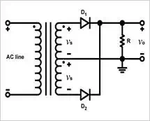
FIGURE 1.3 (A) Full-wave rectifier
circuit; the transformer has a center-tapped
secondary winding
In this configuration, the
step-down transformer's secondary winding is what is called "center-tapped." A center tap,
or CT, is an electrical contact made halfway along the winding. This CT is used
to provide two equal voltages, vS, across the two halves of the
transformer's secondary winding. When the input voltage is positive, both vS signals will also be positive, and when the input
voltage becomes greater than VD, diode D1 will
be conducting and diode D2 will be reverse-biased. The current that flows into diode D1 will also flow through
resistor R and then back to the CT. The circuit behaves just
like the half-wave rectifier during the positive half-cycle of an input
sinusoid.
During the negative
half-cycle, both vS voltages will be negative. Now,
diode D1 is
reverse-biased and diode D2 is conducting. The current that flows through D2 will then flow through
resistor R and back to the CT.
Thus, current flows during
both half-cycles, and furthermore the current through the resistor will always
flow in the same direction. The result is a unipolar output voltage, as shown
in Figure 1.3 (C).
If we consider the circuit's
operation during a positive half-cycle, the voltage at the cathode of D2 is (vS - VD) and the voltage at the anode of D2 is -vS. Thus, the PIV is (VS - VD) - (-VS):
PIV = 2VS - VD
Equation 1.3
Note that this PIV is roughly
double that of the half-wave rectifier.
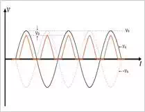
Figure 1.3 (C) Input and output waveforms
Conclusion
In this article, we discussed
the purpose of a rectifier circuit as well as two specific types of rectifiers:
the half-wave rectifier and the full-wave rectifier. Rectifiers are essential
circuits for power supplies that convert an AC input voltage into a DC voltage
supply that can be used to power electronic circuits. We saw that the half-wave
rectifier utilizes alternate half-cycles of the input sine wave whereas the
full-wave rectifier utilizes both positive and negative half-cycles.